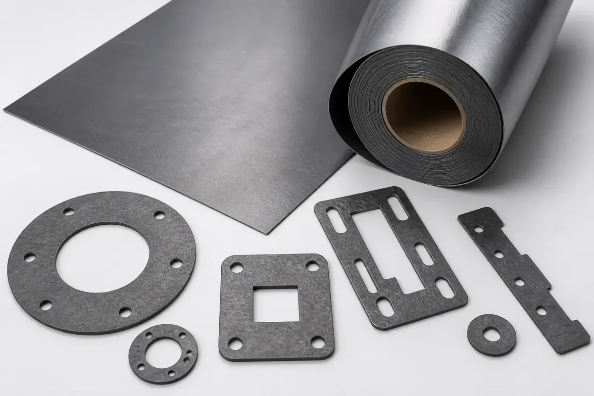
Flexible graphite foil and synthetic thermal graphite sheet can both arrive as thin, dark, electrically conductive layers, but they are not interchangeable products. Flexible foil begins with expanded natural graphite and is calendered into a compressible sheet or roll. Synthetic or pyrolytic thermal graphite starts from a carbon-rich precursor and receives a separate high-temperature treatment that creates a strongly oriented film for lateral heat spreading. The first route also appears in sealing and high-temperature industrial layers; the second is primarily an electronic thermal-management route.
The names used in drawings and purchase orders often hide that distinction. QDZRT Graphite lists graphite paper and flexible graphite sheet as expanded-graphite products, while electronics suppliers may use “graphite sheet” for PGS or another synthetic film. Panasonic explicitly distinguishes natural graphite sheet from PGS, and SGL publishes separate product data for expanded natural graphite foil; see Panasonic’s material distinction and SGL expanded-graphite foil data. Values from one route should not be transferred to the other.
A useful comparison therefore begins with four checks: material family and manufacturing route, heat-flow direction, mechanical behaviour and delivered stack. Those checks prevent an attractive conductivity number from masking the actual requirement. The final assembly sees the graphite core, adhesive, protective film, release liner, exposed edges, placement tolerance and contact pressure together.
The Two Materials Are Different Material Families

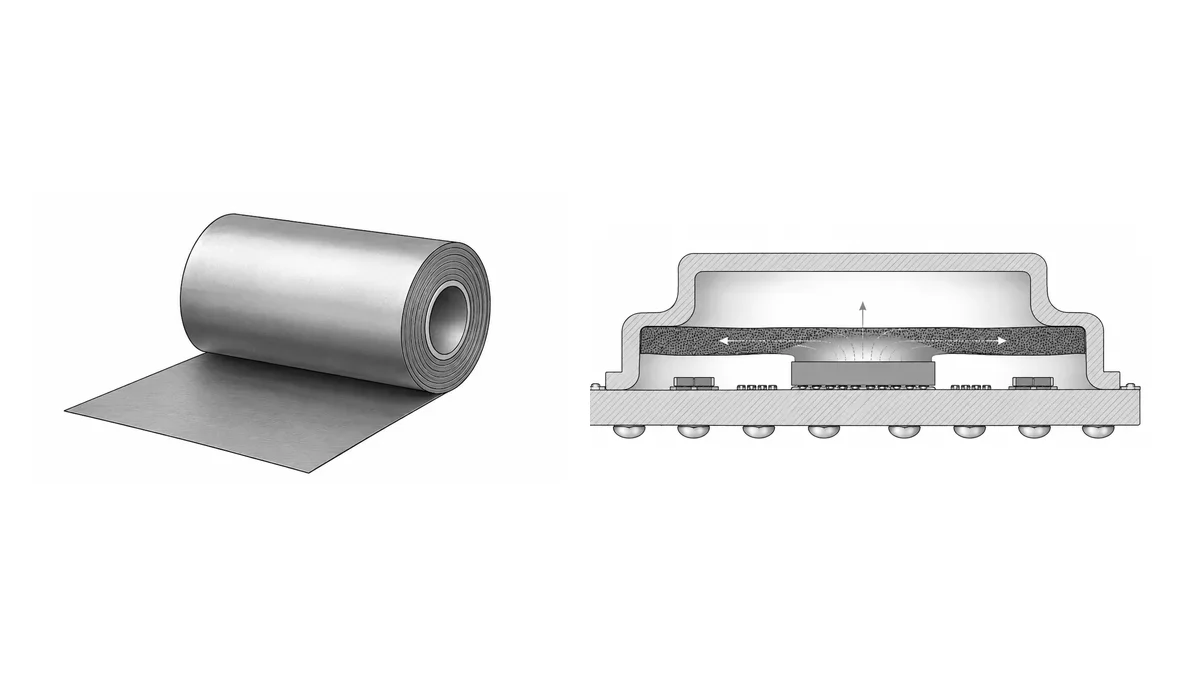
Expanded natural graphite foil contains compressed expanded particles and retains a layered, porous structure. That structure can conform under pressure, follow moderately uneven surfaces and provide a combination of lateral heat spreading and through-thickness contact. Density, calendering, carbon content and any reinforcement or coating change the result. A high-density expanded foil intended for thermal spreading is not automatically the same product as a lower-density sealing foil.
Synthetic or pyrolytic graphite sheet is produced through a different precursor and graphitization route. Its graphite planes are aligned more strongly in the film direction, so specific grades can provide much higher in-plane conductivity at very small thickness. The trade-off is that the bare film is generally less compressible and may need a support film, adhesive or encapsulation for handling. The graphite paper production video shows an expanded-graphite roll route; it should not be used as a manufacturing description for PGS.
A certificate or drawing should identify the route explicitly. For expanded foil, typical fields include raw-material basis, carbon or ash reporting method, density, nominal thickness, roll or sheet dimensions and any surface treatment. For a synthetic film, the data package usually emphasizes grade, film thickness, directional conductivity, layer construction and handling or bend limitations. Common fields such as dimensions, lot identity and visual condition can be shared, but the route-specific fields should remain separate.
| Comparison item | Expanded natural graphite foil | Synthetic or pyrolytic graphite sheet | What the project must verify |
|---|---|---|---|
| Manufacturing route | Expanded natural graphite followed by rolling or calendering | Carbon precursor followed by controlled carbonization and graphitization | Exact grade, manufacturer data sheet and whether the quoted form is bare, coated or laminated |
| Thermal direction | Anisotropic; values depend on density, rolling direction, thickness and method | Strongly anisotropic in specific grades, with high lateral spreading as the primary design function | In-plane and through-plane values, test method, test temperature, specimen orientation and uncertainty |
| Mechanical response | Can compress and conform; edge strength and dust behaviour depend on structure | Thin film bends but may crease, crack or delaminate from support layers | Contact pressure, minimum bend, die-cut geometry, unsupported edges and converter trial results |
| Delivered stack | May be supplied as bare foil, roll, sheet or a project-specific laminate | Often supplied with adhesive, protection film, liner or encapsulation | Shipping thickness, installed thickness, exposed graphite, liner removal and final electrical isolation |
| Published numerical data | Use only values for the named foil grade and density | Use only values for the named PGS or synthetic grade and laminate state | Do not combine the lowest thickness from one grade with the highest conductivity from another |
What a Comparable Data Package Looks Like
A comparison is only credible when both candidates are documented at the same level. The data package should show the exact commercial grade, graphite-core thickness, density or basis weight, directional thermal values, test temperature, test method and the state of the specimen during testing. If one candidate is a bare graphite core and the other is a laminated finished part, the results are not yet comparable. The laminate must either be removed from the property comparison or added to both candidates as a separate stack-level result.
The report should also distinguish typical, nominal and guaranteed values. A typical conductivity value may help with early simulation, but it is not automatically an acceptance criterion. A guaranteed range belongs in the purchase specification only when the supplier has confirmed the method, sampling plan, lot definition and reporting basis. The same distinction applies to thickness, density, surface condition and electrical-insulation performance.
Direction labels need a physical reference. “In-plane” should identify the sheet plane and, where rolling or processing creates an additional direction, the drawing should show machine and transverse directions. “Through-plane” should identify the installed thickness direction. Without that orientation, a high value can be entered correctly in a spreadsheet and still be applied to the wrong axis in simulation.
Traceability also differs between the routes. Expanded foil may be controlled by raw flake lot, expansion and calendering batch, roll number and slit width. Synthetic film may be controlled by precursor film, graphitization batch, master sheet, laminate lot and conversion batch. The purchase order does not need to copy a supplier’s internal process, but it should define the lot identity that will appear on the certificate, label and inspection record.
Structure Determines Where Heat Can Travel
Both material families conduct heat more readily along their graphite planes than through the thickness, but the degree of alignment differs. Expanded foil forms an overlapping network of expanded particles. Synthetic sheet is engineered for stronger planar orientation. This is why two samples with the same nominal thickness may create very different lateral temperature maps even though both are called graphite sheet.
The electronic thermal-management article follows the full route from chip to chassis, while the graphite thermal-management overview separates temperature, atmosphere, load and material form. For a compact electronic assembly, synthetic sheet may be considered when lateral spreading within a very small thickness budget dominates. Expanded foil may be considered when conformability, contact behaviour, industrial temperature or a thicker roll form matters more than the maximum lateral value.
The choice cannot be made from a fixed spread distance. A test plan should define the heat-source size, power map, receiving structure, graphite orientation, interface layers, clamping or bonding method, sensor locations, sampling rate, environmental conditions and steady-state criterion. Simulation can propose the overlap and path; the representative assembly confirms it. Distances and time points used in one device should not become a generic validation rule for all products.
Cutting and handling also follow the structure. Expanded foil can compress under a die and may release carbon at an unsupported edge. Synthetic film can crease or split along a sharp fold and may delaminate from its protective layer. The pad conversion route should therefore treat the final laminate and cut shape as the test article rather than transfer one die rule between the two material families.
Thermal Conductivity Must Be Directional and Grade-Specific
A single unlabelled thermal-conductivity number is not enough. The data line should identify in-plane or through-plane direction, specimen thickness, density, test temperature and test method. Published product sheets show why: specific high-density expanded-graphite foils and specific PGS grades can occupy very different ranges, and even one supplier may offer several grades with different thickness and laminate options.
NASA research on PGS embedded in carbon-fibre polymer composites demonstrates one specialised route for increasing heat transport in lightweight spacecraft radiator structures. It is a useful example of material integration, but it does not validate every bare PGS film, consumer-electronics pad or expanded foil; see the NASA PGS composite-radiator study. The construction, fibre orientation and composite process are part of that result.
An OSTI-hosted study includes a graphite-foil input with approximately 1400 W/m·K in-plane and approximately 14 W/m·K through thickness. Those values belong to the material representation used in that study, not to every product sold as synthetic thermal graphite; see the OSTI graphite-foil study. The useful lesson is the scale of anisotropy, not a universal catalogue value.
The assembled part needs a second level of evidence. Adhesive, contact resistance, surface flatness, pressure and air gaps sit in series with the graphite layer. ASTM D5470 provides a framework for measuring thermal transmission properties of thermally conductive electrical-insulation materials under controlled conditions, but it also relies on an idealised test arrangement; see the ASTM D5470 method. A device programme should correlate material tests with the final assembly.
The test fixture should be chosen after the decision question is written. A material-property test asks for conductivity under a defined method. A spreader comparison asks how the installed part redistributes a known heat input. A device qualification asks whether temperatures, electrical clearances, adhesion and mechanical integrity remain acceptable in the final product. Combining those three questions in one informal bench test usually produces a result that cannot be repeated or transferred.
For a spreader comparison, document the heater footprint, input power and control method, the receiving plate material and thickness, ambient or coolant condition, mounting pressure or adhesive cure, sensor type, sensor attachment, sample orientation and uncertainty. Thermal images can reveal the lateral pattern, but emissivity, reflections and surface coatings must be controlled. Contact sensors can improve traceability, but their mass and placement may disturb a very thin assembly. The approved plan should state how those effects are handled.
Transient and steady-state results answer different questions. A synthetic film may redistribute a short pulse quickly, while an expanded foil may provide more useful contact in a rough clamped interface. The report should not declare one material superior without stating the time window and boundary conditions. Store the raw temperature data, fixture drawing and sample identity together so that a later grade or adhesive change can be compared against the same baseline.
Thickness, Density and Delivered Stack
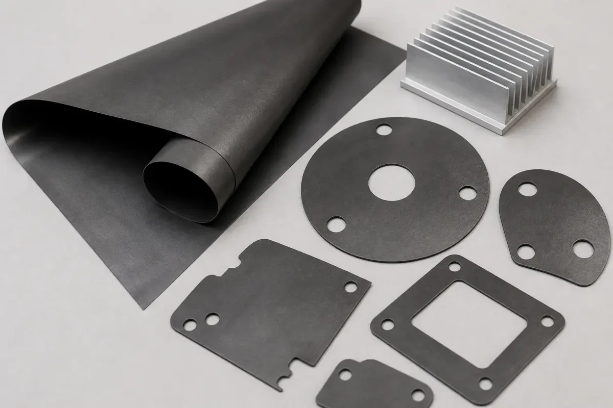
Expanded foil commonly occupies a thicker and more compressible part of the design space, while synthetic films are often selected where the graphite core must be very thin. That tendency does not create a universal thickness range. The nominal graphite thickness, density and tolerance must come from the named grade or drawing. The graphite paper thickness and density guide covers the expanded-material side; synthetic films need their own supplier data.
Areal mass is a useful calculation when its inputs are stated. For example, areal mass equals thickness multiplied by density after units are converted consistently. The calculation can compare two named candidates, but it does not create a product matrix. Protective films, adhesives and liners should be reported separately because they may add more handling thickness than the graphite core.
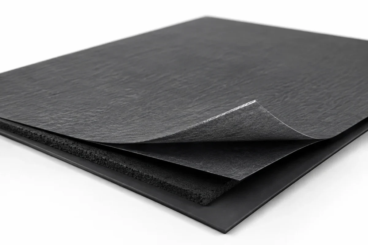
| Stack-up field | Drawing or RFQ input | Measurement or evidence | Why it must remain separate |
|---|---|---|---|
| Graphite core | Material family / manufacturing route, grade, nominal thickness, density and orientation | Supplier data and agreed thickness method or drawing inspection | Core data controls thermal and mechanical behaviour |
| Adhesive | Chemistry, coat side, nominal thickness, release liner and service condition | Adhesive supplier data and finished-laminate validation | Adhesive can dominate through-thickness resistance and temperature limit |
| Protective or insulating film | Film type, thickness, overlap, exposed-edge rule and electrical requirement | Film data, dielectric test and visual inspection plan | A surface film does not make an exposed graphite edge electrically neutral |
| Release liner | Material, thickness, peel direction and removal sequence | Converter trial and packaging instruction | Liner affects die setup and shipping thickness but is absent in service |
| Finished part | Installed thickness, profile, holes, edge seal, placement datum and tolerance | Approved drawing and representative assembly measurement | The device sees the complete stack rather than the bare graphite value |
| Tolerance stack | Layer tolerances and the approved arithmetic or statistical method | Drawing review and process-capability evidence | A root-sum result is not justified without distribution and independence assumptions |
Thickness measurement must also identify the contact pressure and instrument. A compressible expanded foil can report a different value under different measuring force, while an adhesive laminate may include liner texture or local coating variation. The drawing should therefore state whether the controlled value applies to the bare core, finished laminate, shipping stack or installed compressed stack. ASTM D1000 provides test methods for pressure-sensitive adhesive tapes, including thickness-related measurements, but the exact product specification still controls the accepted method; see ASTM D1000.
Conversion trials should evaluate more than whether the outline can be cut. Record edge quality, dust or particle release, liner lift, adhesive squeeze, film cracking, minimum web support, part removal and placement repeatability. A geometry that works during manual sampling may fail in automatic pick-and-place because the liner stiffness, peel direction or static charge is different. Those findings belong in the converter’s DFM record and the approved drawing notes.
Packaging should protect the feature that is most vulnerable. Expanded foil may need support against creasing, edge impact and rubbing. Synthetic film or a finished laminate may need flatness control, clean liners and protection from a fold that damages the graphite core. The packing specification should state orientation, support, interleaf or liner condition, part count determined by the approved pack design and the inspection required after transport.
Electrical Behaviour Is an Assembly Requirement
Both expanded foil and synthetic sheet are electrically conductive. A protective PET or polyimide layer can insulate a surface, but any cut edge, hole or damaged overlap can expose graphite. The final drawing should therefore state working and transient voltage, the applicable electrical standard, creepage and clearance requirements, insulating-film grade, edge encapsulation, dielectric test method and acceptance value.
Fixed voltage or clearance numbers do not belong in a general comparison because the correct value depends on the equipment category, pollution degree, material group, altitude, geometry and final assembly. Panasonic product information distinguishes bare, adhesive-backed and insulated constructions for this reason. Die-cut tolerance and placement tolerance must be included when the available electrical gap is reviewed.
An expanded foil can conform into a burr or sharp edge. A synthetic film can carry current laterally beneath an apparently intact cover. Electrical verification should therefore use the final cut shape and installed stack, not an uncut sheet sample. The graphite paper properties article similarly separates carbon-core behaviour from the behaviour of a complete laminate.
Temperature Limits Belong to the Complete Stack
Expanded graphite foil can serve at elevated temperature when its grade, atmosphere, exposure time and edge condition are controlled. Synthetic thermal sheet is often used at lower device temperatures, but the graphite lattice may not be the first component to fail. Adhesive, PET, polyimide, coating and liner each have their own continuous and short-duration limits.
A published high temperature for a bare PGS core should not be transferred to an adhesive-backed laminate. Product data may state a graphite-core temperature separately from the temperature allowed for an attached tape or insulating layer. Expanded foil also requires an oxidation assessment in air, while inert or vacuum use has a different boundary. The thermal-management and high-temperature solution should be read as a route overview, not a substitute for the exact grade and stack specification.
A validation plan should therefore record continuous temperature, excursion temperature, atmosphere, duration, cycling profile, adhesive ageing, film shrinkage, edge oxidation and post-test inspection. Generic adhesive ceilings, fixed excursion durations and assumed life tests should be removed unless they come from the named product data or the approved programme.
Failure Modes Reveal Which Difference Matters
Expanded foil and synthetic sheet can fail for different reasons even when the measured device temperature initially looks similar. An expanded foil may lose contact if the clamp load changes, wrinkle during assembly, shed particles from an exposed edge or oxidize where air reaches the graphite. A synthetic film may crack at a crease, lift from an adhesive, shrink with a support film or expose a conductive edge after die-cutting. The validation plan should inspect the failure mode expected from the selected route.
A thermal failure is not always a graphite-property failure. A poor adhesive bond, trapped air, misplaced part, contaminated chassis or incorrect contact pressure can erase the advantage of a high-conductivity core. The report should separate material-property evidence from conversion evidence and assembly evidence. That separation makes corrective action clearer: change the graphite grade only when the graphite property is actually controlling.
Mechanical inspection should be linked to the application. For a compressed expanded foil, record installed thickness, witness pattern, edge condition and any permanent set. For a synthetic laminate, inspect crease lines, film overlap, adhesive coverage, delamination and exposed graphite. For both routes, compare the used part with an uninstalled sample from the same lot and preserve photographs or microscopy where the failure location is not obvious.
A controlled material change should repeat only the evidence affected by the change. A new graphite-core grade may require thermal and mechanical comparison. A new adhesive may require thermal resistance, peel, ageing and electrical checks. A change in liner or die-cut geometry may primarily affect conversion yield and placement. Defining that logic in advance reduces unnecessary testing without turning a supplier change into an unreviewed substitution.
Cost Should Be Compared per Accepted Finished Part
Expanded foil may be quoted by roll, sheet, weight or square metre. Synthetic film is often evaluated by square metre or finished die-cut part because the mass per device is small. Price per kilogram therefore gives a distorted comparison. The useful basis is accepted finished area or accepted finished part after conversion and inspection.
The cost model should not contain invented material indices, edge losses, nesting yield, scrap rates, order quantities or packing counts. Those inputs belong to the buyer and converter. The graphite roll and sheet packaging article explains why damage and packaging affect usable area, but each programme still needs its own records.
| Cost input | Buyer or supplier source | Calculation basis | Evidence to retain |
|---|---|---|---|
| Base graphite material | Current quotation for the named grade and dimensions | Purchased area, roll or sheet | Quotation revision and specification |
| Lamination and films | Converter quotation | Finished laminate area | Layer definition and process scope |
| Slitting and die-cutting | Tooling and production quotation | Accepted parts, not machine strokes | Tool life, setup and inspection plan |
| Yield and scrap | Approved nesting and trial results | Accepted area divided by invoiced area | Nesting drawing and lot yield |
| Validation and change control | Project test plan | Programme cost or amortised approved quantity | Test reports and approval status |
| Packing and logistics | Supplier and logistics quotation | Accepted delivered parts | Packing standard and transport-loss record |
Choosing One for a Real Assembly
Expanded graphite foil is a candidate when the assembly needs conformability, compression, thicker roll or sheet forms, industrial temperature capability or a combined spreading-and-contact role. Synthetic thermal graphite is a candidate when lateral spreading is dominant, the thickness budget is severe and the assembly can manage the film’s handling, insulation and edge requirements. These are screening directions, not automatic selections.
Write the two candidates as complete stack-ups. Record material family / manufacturing route, grade, graphite thickness, density, directional conductivity, adhesive, protection film, liner, installed thickness, electrical isolation, continuous and excursion temperature, atmosphere and annual accepted area. Then compare the measured temperature map, mechanical fit, electrical result and delivered cost under the same boundary conditions.
Related forms can be reviewed through the graphite products category and the graphite sealing materials page. QDZRT Graphite can quote expanded-graphite foil or sheet within the documented supply scope. Synthetic-film selection, lamination, insulation and conversion responsibilities should be confirmed among the buyer, converter and supplier in the drawing and quotation rather than inferred from a general article.
Send the assembly cross-section, target temperature map, electrical constraints and annual area through the contact page. The purpose of the enquiry is to identify the exact product family / construction and supply boundary before comparing price or conductivity.