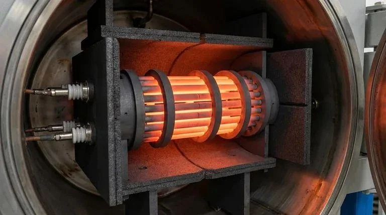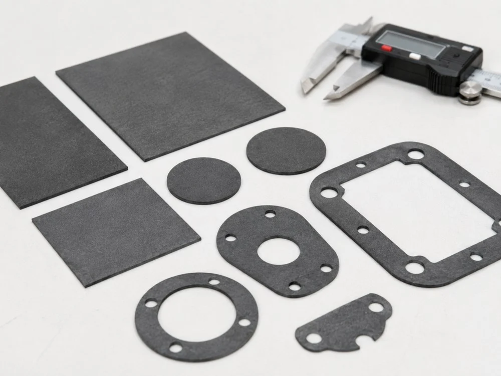
A finished heat-spreading pad begins as a roll, not as a perfect outline on a drawing. The conversion route changes the material at every station: the master roll is inspected and slit, optional adhesive or protective film is laminated, the full stack is die-cut, the pad is installed, and the completed assembly is validated. QDZRT Graphite supplies graphite paper in roll or sheet form and can review slit-roll, laminated or converted requirements when those forms are included in the confirmed project scope. The final pad, however, must be approved against the buyer’s drawing, converter process and actual assembly.
This distinction matters because conversion does not merely reduce a roll to a smaller shape. Slitting can create edge damage; lamination can trap particles or air; die-cutting can weaken narrow bridges; liner removal can stretch a thin part; and assembly pressure can change the contact condition. The material, adhesive, protective film, release liner, tool and device therefore form one controlled stack. A dimensional pass at the die-cut station does not by itself prove thermal performance, electrical separation or long-term adhesion.
The article focuses on expanded-natural-graphite paper used as a flexible conversion material. Synthetic or pyrolytic thermal graphite sheets belong to a different material family, even though both may be used to spread heat. The comparison in flexible graphite foil and synthetic thermal graphite sheet explains why a converter must identify the exact grade before assigning process settings. A thermally annealed pyrolytic graphite study from OSTI evaluates a specific power-module heat-spreader configuration; it supports the general importance of directional heat spreading but does not validate every expanded-natural-graphite pad or grade supplied by our team. See the OSTI report on the TPG power-module heat spreader.
The Six-Stage Roll-to-Pad Control Chain
A useful conversion plan treats each stage as an input-output gate. The next operation accepts the previous operation’s measured condition rather than assuming that the nominal drawing is still true. The receiving record confirms the roll identity. The slitting record establishes usable lane width and edge condition. The lamination record identifies the exact tape, film and liner. The die-cut record controls geometry and tool condition. Assembly records placement and load. Validation connects the finished pad to the actual thermal, mechanical and electrical requirement.
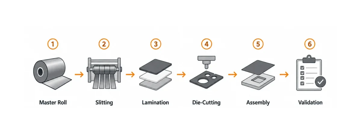
| Stage | Controlled input | Required output | Approval evidence |
|---|---|---|---|
| Master roll | Grade, lot, thickness, density, width, winding and packaging condition | Released roll with traceable usable width and mapped defects | Receiving inspection and lot record |
| Slitting | Approved roll, target lane layout, equipment and winding direction | Slit rolls with measured width, edge condition and winding history | First-piece and in-process width/edge report |
| Lamination | Named adhesive, film, liner, substrate and conditioning plan | Qualified laminate without unacceptable bubbles, offset or contamination | Material certificates, setup record and laminate inspection |
| Die-cutting | Full stack, controlled drawing, tool, cut type and sampling plan | Parts meeting geometry, edge and liner requirements | First article, in-process checks and tool-life record |
| Assembly | Approved pad, orientation, datum, load or stop and clean mating surfaces | Correctly placed stack without fold, trapped debris or unintended contact | Assembly instruction and build record |
| Validation | Completed assembly and approved test conditions | Documented thermal, mechanical and electrical result | Test report and authorized disposition |
Where the Pad Sits in the Assembly
The pad sits between a local heat source and a larger surface that can accept and reject heat. In a compact electronic assembly, that surface may be a frame, shield can, battery enclosure or chassis plate. The graphite layer does not replace the complete cooling system. It redistributes a concentrated heat load over a larger in-plane area, while the interfaces, metal structure, airflow and final heat sink still determine the overall result. The thermal-management material solution and the electronic thermal-management article provide the broader application context.
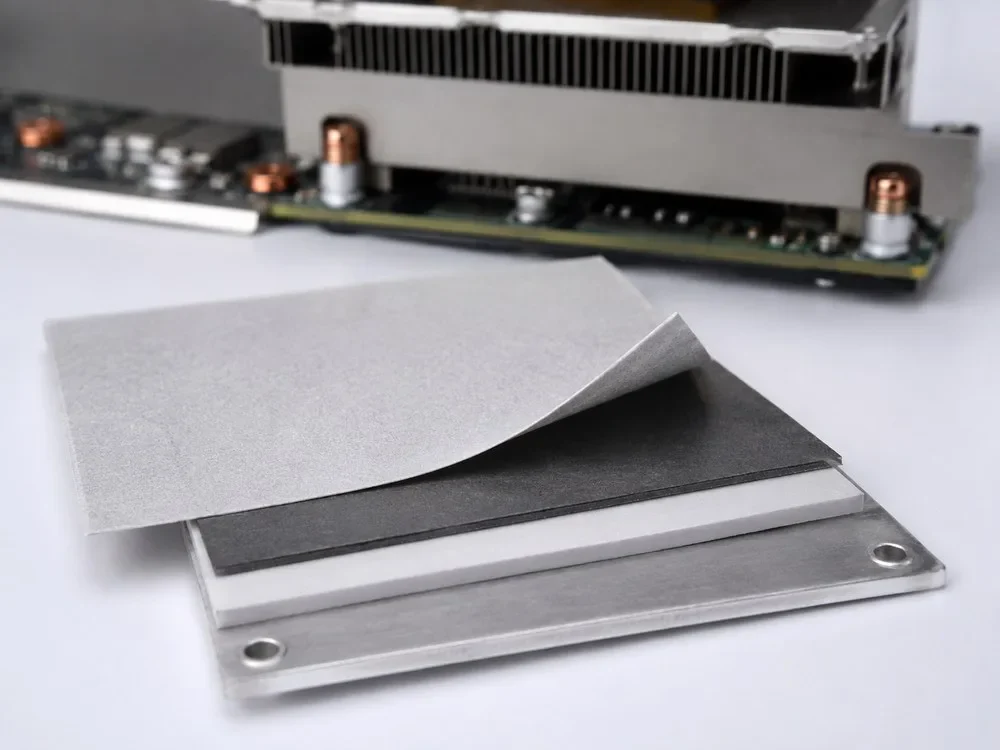
The first drawing review therefore starts with the layer stack, not only the outer profile. A 0.05 mm graphite layer under a 0.05 mm adhesive and a 0.075 mm release liner is a 0.175 mm temporary converting stack. After the 0.075 mm liner is removed, the nominal installed stack becomes 0.10 mm before any assembly compression. This arithmetic is correct, but it does not prove that this combination is available, compatible or qualified. Each layer must be identified by grade or supplier designation, and the total construction must be confirmed through an approved sample.
A pad may contact the heat source directly, sit beside it, bridge to a frame or wrap around an edge. Those positions do not impose the same demands. Direct contact makes surface cleanliness and contact pressure prominent. A side-mounted spreader depends more heavily on in-plane distance and attachment. A bridge across a gap requires sufficient support. An edge wrap adds bending and spring-back. The drawing should therefore state the heat-source footprint, intended heat-flow direction, contact area, stack order, adhesive coverage, compression or stop condition, and any electrical keep-out boundary.
Illustrative stack builds—not standard products
The values below are retained as teaching examples. They show how temporary converting thickness differs from installed thickness and how liner removal changes the stack. They do not state that every graphite thickness can be combined with every adhesive, film or liner, and they do not define universal 5%, 10% or 15% compression classes.
| Illustrative build | Graphite | Adhesive | Protective film | Release liner | Required project confirmation |
|---|---|---|---|---|---|
| A | 0.025 mm | 0.025 mm | 0.025 mm | 0.050 mm | Grade availability, tape model, film function and handling trial |
| B | 0.050 mm | 0.050 mm | 0.050 mm | 0.075 mm | Total thickness, peel/release method, service temperature and assembly test |
| C | 0.100 mm | 0.100 mm | 0.075 mm | 0.100 mm | Bendability, die-cut geometry, electrical requirement and approved sample |
A protective film controls electrical separation only when the exact film and complete construction have a suitable dielectric rating and pass the required assembly test. Graphite itself is electrically conductive. “Protective film” is therefore not a synonym for “approved electrical insulation.” Similarly, a nominal compression percentage is only arithmetic until the assembly defines the force or pressure, stop height, compression curve, creep or relaxation allowance, and verification method.
From Master Roll to Slit Roll
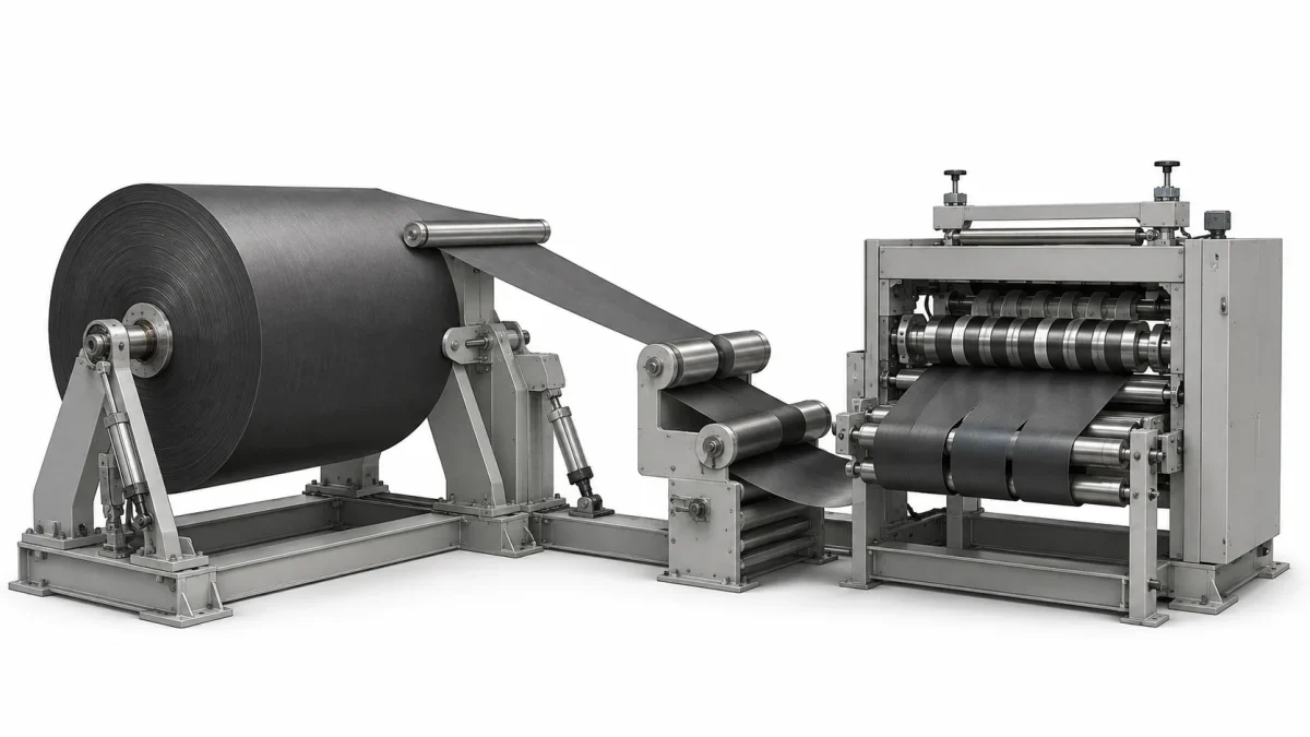
The master roll first becomes a working web. Receiving inspection should confirm the purchase order, grade, lot, width, thickness, density, surface condition, edge condition, winding direction and packaging evidence before conversion. The related guide to incoming roll-quality inspection explains why an unidentified or damaged roll should be quarantined rather than allowed to enter production.
Slitting establishes edge reference and divides the width into lanes. A 500 mm roll converted into four 120 mm lanes leaves 20 mm for edge trim and knife loss. Five nominal 100 mm lanes leave no allowance at all. The 20 mm arithmetic remains useful because it exposes an RFQ omission, but the final lane plan must also include edge trim, knife kerf, registration allowance, mapped defects and any unusable side. Usable yield must be calculated from the approved roll and actual tool layout rather than from nominal width alone.
Core IDs such as 76 mm or 152 mm and web widths such as 250, 500 or 1000 mm can be legitimate procurement inputs, but they are not low, medium and high process levels. The chosen core must fit the unwinder, winding torque and roll diameter. Slit tolerance and line speed must be qualified for the selected graphite grade, full laminate, roll condition and machine. A 2 m/min trial may be appropriate on one line while a different line or stack requires another starting point.
Thin expanded graphite has little resistance to a damaged edge. A nick introduced during unpacking may propagate when web tension rises. Excess braking can distort a support film or liner; insufficient tension can allow wandering and irregular slit width. The slit-roll record should include actual width at approved locations, edge feathering or cracking, telescoping, winding tightness, splice locations and the disposition of mapped defects. Width lost at slitting cannot be restored by lamination.
Adhesive, Protective Film and Release Liner
Adhesive backing makes assembly faster, but it turns a single flexible layer into a multilayer web with different stiffness, thermal resistance and dimensional behaviour. The conversion specification should identify the adhesive supplier and model, nominal thickness or coat weight, carrier construction, liner type, storage limits, service-temperature range and the intended mating substrate. A generic note such as “50 µm adhesive” cannot predict peel, shear holding, outgassing, repositionability or long-term bond behaviour.
A named product page, such as 3M 467MP adhesive transfer tape, illustrates why the precise tape designation matters: products in the same family can differ in adhesive thickness, liner construction and available format. The product page is not a recommendation for every graphite pad. It is an example of the level of identification required before lamination trials begin.
Peel and release values also require test conditions. ASTM D3330/D3330M covers peel adhesion of pressure-sensitive tape, while ASTM D3652/D3652M addresses tape thickness. The approved plan must still define the substrate, sample width, peel angle, peel speed, dwell or conditioning time, test temperature and whether the measurement is tape-to-substrate peel or liner release. Where static shear holding is critical, the project should add an agreed shear method and acceptance rule.
The liner supports the graphite through slitting and die-cutting, affects flatness in the pack and determines whether a kiss-cut stops above the final support. A PET liner and a paper liner do not respond identically to humidity. Conditioning values such as 2, 24 or 48 hours and 40%, 50% or 60% RH are therefore trial points, not universal requirements. The approved project should state the conditioning environment, time, measurement sequence and release criteria.
Project-controlled conversion trial matrix
| Control | Illustrative starting points retained from the original guide | Project variable | Evidence for release |
|---|---|---|---|
| Core and web | 76/152 mm core; 250/500/1000 mm web | Equipment fit, roll diameter, winding torque and usable width | Incoming and setup record |
| Slitting | ±0.20/±0.30/±0.50 mm; 2/5/10 m/min | Grade, full stack, knife, tension, lane geometry and equipment capability | Measured width, edge map and approved process window |
| Adhesive/liner | 25/50/100 µm adhesive; 50/75/100 µm liner | Named product, substrate, release method, temperature and storage | Supplier data, measured stack and qualified laminate |
| Conditioning | 2/24/48 h; 40/50/60% RH | Film, liner, adhesive, climate and measurement sequence | Curl, release and dimensional results |
| Disposition | No universal value | Drawing, risk, trial results and approved sample | Authorized approval, concession, rework or rejection |
The original numbers remain useful as a DOE-style set of starting conditions, but the trial must record the actual equipment, graphite lot, tape lot, film lot, tool, operator, environment and result. A three-level table is not a specification unless the buyer and converter have qualified those exact levels and defined how the final setting is selected.
Die-Cutting the Full Stack
Die-cutting converts a continuous laminate into many small stress concentrations. Every hole, corner and narrow bridge asks the graphite, adhesive and liner to survive a new edge. A broad rectangle is more forgiving than a 1.5 mm hole beside a 1.0 mm bridge. Those dimensions are useful as an illustrative difficult feature, not as a universal minimum. The controlled drawing should define minimum web, minimum hole, corner radius, adhesive setback, release tab, kiss-cut or through-cut, matrix-stripping method and any no-dust or cosmetic zones.
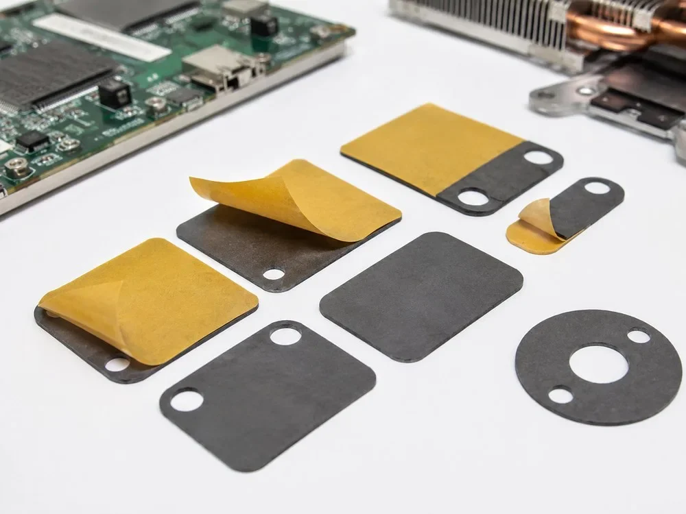
The tool is set against the entire temporary stack. In the earlier arithmetic example, a 0.10 mm graphite layer, 0.05 mm adhesive and 0.075 mm liner create a 0.225 mm converting stack. A kiss-cut intended to leave the liner intact must cut through the graphite and adhesive without unacceptable scoring of the support. The allowable score depth and liner integrity need a measurable criterion. Variation across the web, die pressure and tool wear should be included in first-article and in-process checks.
Ten to twenty impressions can remain as an illustrative first trial. A practical review can inspect early, middle and late positions across the die width for outline dimension, hole clearance, edge feathering, liner damage and matrix removal. A production run of 5000 pieces remains a useful reminder that adhesive buildup and tool wear may appear after the first clean parts. The actual trial quantity, sampling interval and stop rule must be established from geometry, batch size, tool history and risk. A clean first impression is evidence for setup, not proof of sustained production capability.
Assembly Compression, Contact and Electrical Boundaries
At assembly, the liner is removed and the thin part can be difficult to reposition. The operator needs a clear peel tab, visible orientation for asymmetric shapes and a datum that remains usable after nearby components are installed. A fold doubles local thickness and creates an adjacent gap. A trapped particle can produce a local high point. An aggressive liner release can stretch a narrow bridge. These risks should be tested using the real assembly method rather than judged only from a flat drawing.
If a nominal 0.20 mm installed stack is described as compressed by 10%, the arithmetic target is 0.18 mm. That calculation should be treated as a controlled example. Real compression depends on the force or pressure, loaded area, mating-part flatness, stop height, adhesive flow, graphite compression curve and time-dependent relaxation. Contact often improves as air gaps close, but excessive or uneven load can damage a thin stack or move adhesive. The approved design therefore needs measured force/pressure, compression and recovery data, creep or relaxation review, and a thermal test in the intended contact geometry.
Electrical separation requires separate evidence. Graphite is conductive. A pad near exposed contacts may need a verified insulating film, a controlled keep-out zone or a reduced outline. The film’s supplier rating must match the required voltage, thickness, temperature and test method, and the full converted stack should be checked after cutting and assembly. The wider graphite thermal-management overview covers material forms, but only the project drawing and validation plan can define an inspectable isolation boundary.
Clean Handling and Occupational-Hygiene Scope
Expanded-natural-graphite conversion can release dust during opening, slitting and trimming. NIOSH lists natural and synthetic graphite separately. The NIOSH natural graphite entry is the more relevant background source for an expanded-natural-graphite roll, while the synthetic graphite entry should be consulted when the material is synthetic. The NIOSH Pocket Guide introduction describes the guide as general industrial-hygiene information; it is not a complete site-specific converting SOP.
The facility should therefore use the selected graphite SDS, adhesive and film SDS, exposure assessment, equipment design and applicable local rules to establish extraction, housekeeping, PPE and waste controls. Avoiding compressed-air blow-off is a sensible contamination and dust-control measure where it could spread particles, but the exact cleaning method must be approved for the line and product. Adhesive faces and cosmetic surfaces should remain protected from carbon particles, oil, fibers and handling marks.
Validation and Failure Feedback
Service failure rarely begins with graphite simply “losing conductivity.” More common visible symptoms include a lifted corner, laminate separation, a torn bridge, migration, a folded edge, contamination or a change at the bond line. Thermal cycling can amplify a weak interface because graphite, adhesive, film and metal housing do not respond identically. A pad across a sharp step may crack at that line. A pad wrapped around a tight radius may spring back. A tape can retain adhesion while a film, liner or surrounding component was not qualified for the same temperature.
Finished-pad validation should therefore match the intended function. It may include dimensional checks, stack thickness before and after liner removal, adhesion or release, compression and recovery, electrical isolation when applicable, thermal performance under realistic pressure, cleanliness and visual inspection. Acceptance criteria and sample size must be established in the approved validation plan. Results from one stack, pressure or device cannot be transferred automatically to another.
Packaging can also reverse conversion quality. Excessive stack height may imprint lower pieces; loose packaging can let narrow parts slide and catch at corners. The export packaging guide for graphite paper explains roll and sheet protection, but finished pads need a project-specific count, separator, orientation and pack height. A service investigation should compare retained samples with returned parts and record failure location, operating time, temperature exposure, assembly pressure and whether adhesive remained on the graphite or transferred to the mating surface.
RFQ and Responsibility Boundaries
A drawing that converts cleanly includes the finished outline, datum system, material direction, layer construction, exact graphite grade, adhesive coverage, tape designation, film and liner, cut type, release tab, part orientation, packing count and controlled revision. It should also identify the actual heat source, contact area, insulation boundary, assembly method, service temperature, expected volume and trial quantity. The graphite paper thickness and density guide helps define upstream material inputs, while the graphite paper properties and use guide explains why grade and thickness affect converting behaviour.
Revision discipline is essential because the converter may use separate tool, liner, inspection and packing documents. The approach described in global graphite project communication helps prevent a revised outline from being quoted against an obsolete layer stack. Useful supporting material includes a device cross-section, marked heat-source image, assembly load or stop, and the required electrical boundary.
For upstream context, the graphite paper production video and custom production-line video show where roll form begins. The request may also reference the wider graphite product range or flexible graphite sheet when another material form is being considered.
| Party | Typical responsibility | Required approval |
|---|---|---|
| Our team | Supply the confirmed graphite material or agreed converted form; provide order-defined inspection and documentation | Confirmed quotation, specification and purchase order |
| Converter | Qualify slitting, lamination, die-cutting, cleaning, inspection and packing for the approved construction | Approved sample and process-control plan |
| Buyer/device engineer | Define the functional requirements and approve the finished pad in the actual device | Drawing, validation criteria and final release |
Start the inquiry through the contact page with the layer stack, trial quantity and service conditions. After we reply, send the controlled drawing and other project files by email or another agreed secure channel. QDZRT Graphite can then review roll, sheet, slit-roll, lamination or die-cut requirements that are included in the confirmed project scope. The converter and buyer remain responsible for validating the finished pad and the complete device assembly unless the contract explicitly assigns additional responsibilities.