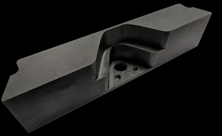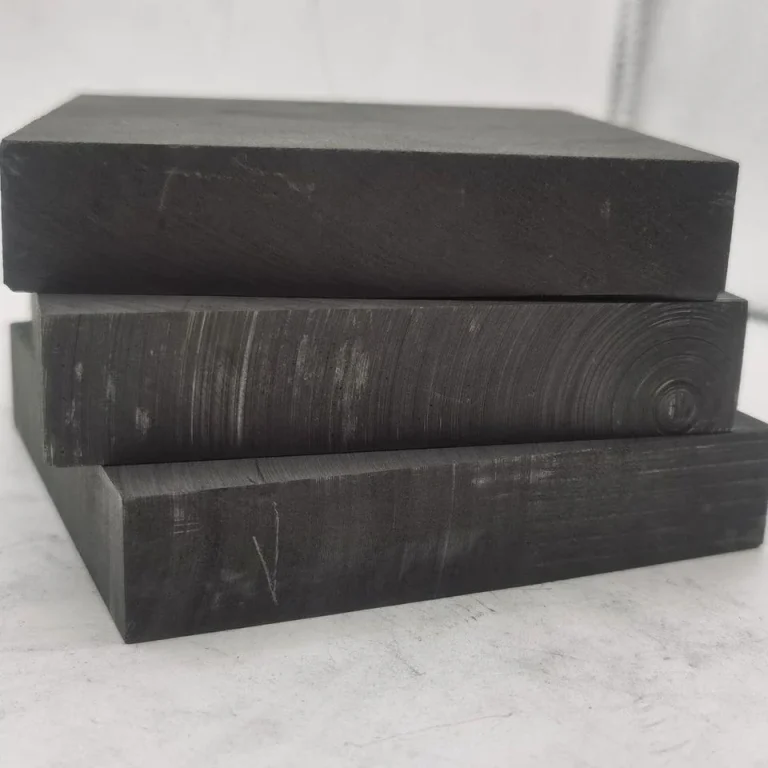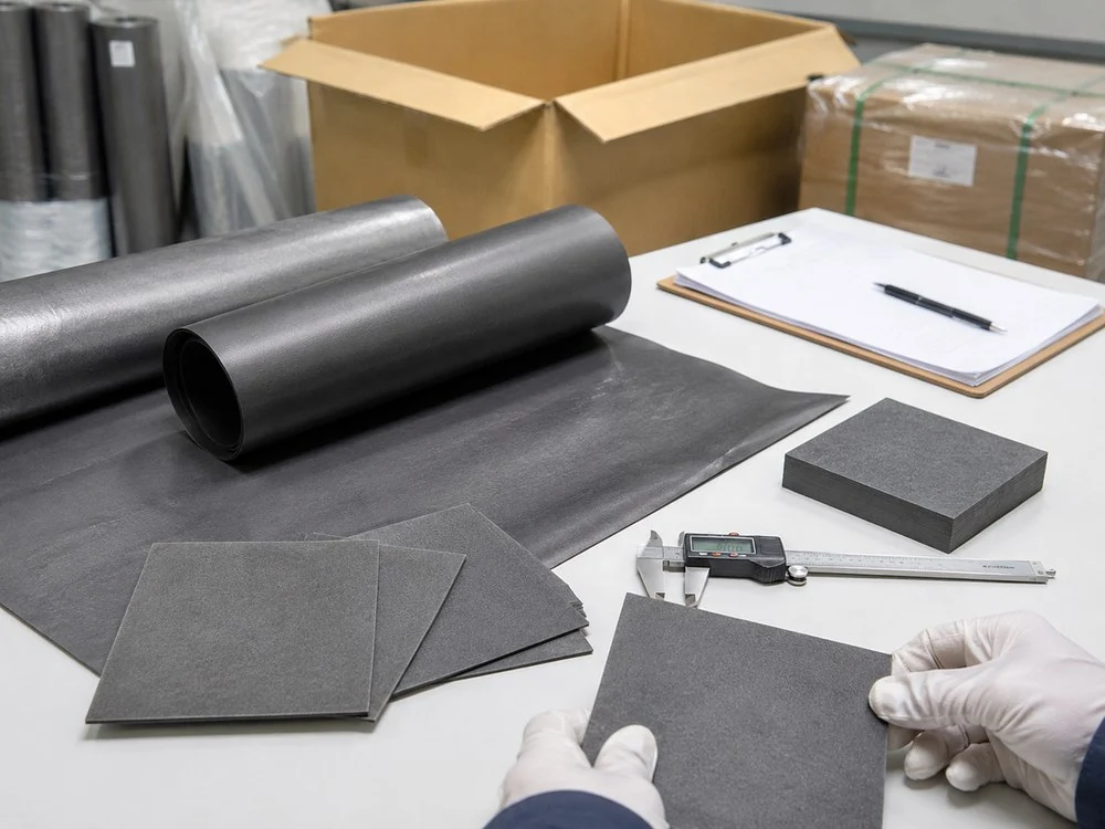
A die-cutting line should not be the first place where a roll of graphite paper is judged. Incoming inspection confirms four things before production: the delivered roll is the approved material, transport has not changed its usable condition, the measurement method is capable of judging the agreed specification, and a short conversion trial behaves within a written process window. The inspection is therefore a controlled release decision made against the agreed specification and process window. It does not reduce to one universal pass/fail number.
The method must match the finished part. A 500 mm-wide roll intended for 20 mm rectangles can tolerate a different defect location from the same roll intended for a 480 mm-wide heat spreader. The graphite paper conversion route shows how incoming width, surface condition, liner, adhesive and die layout affect finished yield. The receiving record should identify the approved product code, roll number, usable width, part layout, critical zones and the controlled inspection plan that applies to that order.
Expanded natural graphite can release dust during opening, cutting and sampling. Published occupational guidance supports hazard review but does not replace the safety data sheet, site risk assessment or local rules. Extraction, cleaning, PPE and compressed-air restrictions are defined for the actual roll construction.
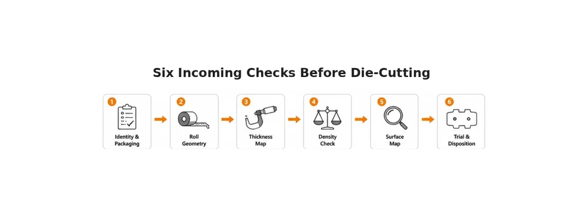
1. Confirm Identity and Preserve Packaging Evidence
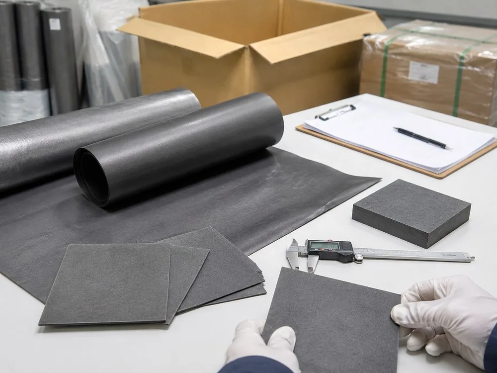
Before cutting stretch wrap, compare the pallet, carton and roll labels with the purchase order and approved specification. Record the product name, grade or unique code, nominal thickness, density range, width, roll length or net weight, batch number, roll number and carton number. Photograph the unopened package. A missing or conflicting identity field is a traceability stop: isolate the roll until the supplier and buyer identify the controlled record.
Inspect the carton or case for punctures, water marks, compression, tilt and displaced supports. Measure and photograph any damage before opening. The export packaging article explains common transit risks such as core collapse, telescoping and crushed edges. The receiving form should record the damaged face, measured area, package orientation and whether the inner barrier remains intact. A hole size or dent depth is evidence; it is not by itself a universal accept or reject threshold.
Cut straps and film away from the roll edge, support the roll on a clean cradle and retain the first damaged wrap until photographs and measurements are complete. Check the core in several directions, measure layer shift at both ends, inspect the edge profile and identify the actual usable width. The acceptance limit comes from the purchase order, packaging specification, approved roll drawing and converter layout. A local edge loss may be removable when the order permits a reduced usable width or compensating length; the same damage is unacceptable when it crosses the only functional lane.
| Incoming control | Record | Project acceptance source | Initial disposition |
|---|---|---|---|
| Identity and batch | PO, approved code, batch, roll and carton | Purchase order and controlled specification | Quarantine any mismatch or unreadable identity |
| Package condition | Location, size, photographs and inner-barrier condition | Packaging specification and transport claim procedure | Hold when product exposure cannot be excluded |
| Core and telescoping | Core diameters, end displacement and unwind stability | Approved core, handling and unwind requirements | Hold for controlled unwind or expanded inspection |
| Edge damage and usable width | Maximum damaged width and remaining lane width | Finished-part layout and usable-width requirement | Review trim, compensation, concession or return |
| Moisture evidence | Outer and inner layer condition, stains and exposure path | Material, liner and adhesive storage specification | Quarantine pending material review |
This table is an RFQ and receiving-control framework. It deliberately does not prescribe one hole size, core ovality, telescoping amount or edge-crush value for every roll. Those numbers belong in the approved inspection standard for the actual construction and conversion route.
2. Map Thickness With an Approved Low-Force Method
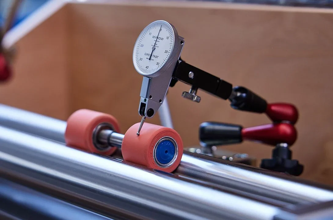
Flexible graphite can be indented by the measuring system. The inspection plan should identify the instrument, contact force, anvil geometry, display resolution, calibration status, operator technique and any conditioning requirement. A sharp caliper jaw or uncontrolled spindle force can create a false low result. Display resolution alone is not sufficient evidence of measurement capability. Repeatability, bias and measurement uncertainty must also be suitable for the tolerance being judged.
A cross-web map remains useful. Mark left, quarter-left, centre, quarter-right and right positions while keeping edge points inside the declared usable width. Repeat the line at agreed length positions. For one converter, three five-point lines may be a practical first-article map; another order may require fewer or more points because the roll is shorter, wider, higher risk or historically less stable. The approved sampling plan should use lot size, risk, process history and the consequence of a missed defect rather than nominal thickness alone.
ISO 2859-1 provides an attributes-sampling framework, while ISO 3951-1 covers sampling by variables for measurable characteristics under defined conditions. Neither standard means every graphite roll must use one AQL, sample count or acceptance number. The buyer must define the inspection level, lot formation, switching rules and disposition in the quality plan. For thickness methodology, ISO 534 and ASTM D374/D374M illustrate that thickness methods specify apparatus and procedure within stated material scopes. Their applicability to a named flexible-graphite construction must be confirmed rather than assumed.
Record every individual reading, since the average alone can mask meaningful variation across the web. A set of 0.098, 0.100, 0.101, 0.099 and 0.102 mm is centred near 0.100 mm and also shows the cross-web spread. A single 0.112 mm result may matter to a kiss-cut, lamination or stack-height requirement even when the average passes. Zero the gauge before the map, check it with a suitable reference after the map, record instrument ID and calibration date, and avoid pulling the web under tension during measurement.
When one point is outside the approved band, isolate the roll and follow the written escalation rule. That rule may require repeat measurement, another operator, an expanded map, confirmation with a reference method or supplier review. Production urgency is not a measurement decision.
3. Check Apparent Density Against the Named Grade
For incoming inspection, we determine density from sample mass, measured area and average measured thickness under the approved method. The result is compared with the ordered grade, certificate and agreed test method; a catalog value from an unrelated product is not an acceptance criterion.
For a transparent arithmetic example, a 100 mm × 100 mm sample has an area of 100 cm². At an average thickness of 0.10 mm, or 0.01 cm, its volume is 1.0 cm³. A mass of 1.20 g therefore gives an apparent density of 1.20 g/cm³. If the actual measured thickness is 0.095 mm, or 0.0095 cm, volume becomes 0.95 cm³ and the same mass gives about 1.26 g/cm³. The calculation is correct only when dimensions, thickness contact conditions and mass are controlled.
Sample size, balance readability, number of replicates, conditioning time and allowable spread are method fields that depend on the product and construction being tested. A 50 mm sample may be adequate for one thin and uniform roll but too sensitive to edge quality or cutting loss for another construction. Likewise, a fixed difference of 0.08 g/cm³ cannot be used as a general non-uniformity limit. The approved plan should state the grade range, calculation units, replicate rule and action when the certificate and receiving result disagree.
The differences between expanded natural graphite foil, laminated graphite products and synthetic thermal sheet are reviewed in flexible graphite foil versus thermal graphite sheet. Incoming inspection must not transfer a density or thickness expectation from one product family or construction to another.
| Plan field | What must be approved | Why it matters |
|---|---|---|
| Thickness map | Positions across width and along roll length | Detects local and directional variation relevant to the part layout |
| Thickness tolerance | Named grade, drawing revision and test method | Prevents catalogue or example values becoming the order limit |
| Density sample | Dimensions, conditioning, thickness method and replicate count | Controls the calculated volume and comparability |
| Balance and gauge | Range, readability, calibration and uncertainty | Confirms the equipment can support the decision |
| Trial quantity | Geometry risk, lot size, process history and defect class | Connects incoming data to actual conversion behaviour |
4. Inspect Surface, Edges and Splices by Coordinates

Use angled light and a controlled unwind to look for scratches, embedded particles, oil marks, loose powder, wrinkles, pressure bands, splice tape and local gloss changes. Photograph representative conditions and mark each defect by distance from the left usable edge and distance from the roll start. “Scratch near centre” cannot be matched to a die layout; “scratch from 238–246 mm across width, beginning at 6.4 m and ending at 7.1 m” can.
Judge defects against the finished-part layout and defect classification. An 8 mm scratch can be harmless in a trim lane and critical when it crosses every 6 mm pad lane. Define Critical, Major and Cosmetic categories, the permitted zone, maximum count or length, and the authority that may grant a concession. The graphite paper properties article explains why layered graphite marks and tears differently from a plastic film; the incoming acceptance rule still comes from the controlled drawing and conversion plan.
Splices need a separate rule. Record count, position from roll start, tape width, flagging method and any length allowance. When the die-cutting line cannot pass a splice, the order should state whether splices are prohibited or whether each splice requires an identified stop and compensation. Defect coordinates are justified by traceability and nesting control; a thermal-anisotropy reference is not needed to prove this receiving method.
5. Run a Controlled Short Die-Cut Trial
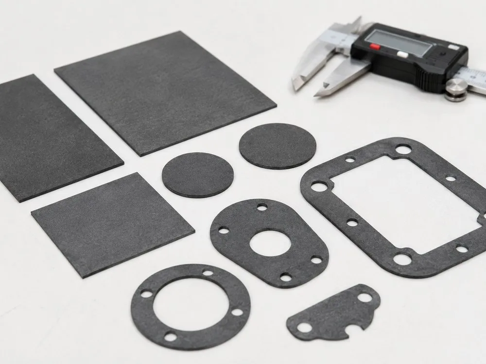
The short trial connects inspection data to production behaviour. Use the approved die or tool, backing or liner, web support and cutting method where practical. When the normal construction includes adhesive and release liner, identify whether the trial uses raw graphite, laminated stock or both. Record speed, pressure, depth or clearance, unwind tension, matrix-removal method and environmental conditions that affect the result.
Trial quantity is risk-based. Twenty, fifty or one hundred parts may be useful illustrative quantities, but none is a default standard. The plan should define where samples are taken during the run, which critical dimensions are measured, how edge chips, incomplete cuts, liner strikes, delamination and matrix-removal tears are classified, and what condition stops the trial. A speed comparison such as 1 m/min versus 10 m/min is meaningful only when the machine, tool, geometry and other settings are held and recorded.
For thermal pads, inspect flatness after release and compatibility with the intended adhesive or stack. The electronic thermal-management article and graphite thermal-management overview explain why the delivered stack matters. Incoming inspection does not certify device thermal performance; it verifies that the received material can enter the approved conversion process.
Set the limits before cutting. An illustrative 50-part plan might require zero incomplete outlines, all measured critical dimensions inside the drawing tolerance, no cut-through of the release liner and a pre-agreed edge-chip count. Those values are examples only. The controlled plan must identify the drawing revision, defect definitions, sample count, acceptance number, stop condition and approver.
6. Example of a Project-Controlled Inspection Plan
Consider a converter receiving a named 0.10 mm expanded-natural-graphite grade for a narrow thermal-pad program. The purchase order might define nominal thickness and tolerance, minimum usable width, permitted splice conditions, approved density band, roll identification and packaging requirements. The converter’s quality plan then adds the measurement method, map positions, sample count, defect classes, short-trial geometry and disposition authority. These two documents work together: the material specification defines what was purchased, while the inspection plan defines how the receiving team will judge it.
The thickness map may use three cross-web lines for the first delivery because the supplier and converter do not yet have shared capability data. After several conforming lots, the approved plan may reduce or redirect sampling; after a trend or complaint, it may increase sampling. That change must be documented. It should not occur informally after the inspector sees a convenient result. The same principle applies to density replicates, splice checks and trial quantity.
Suppose one edge has 7 mm of visible damage. That number alone does not decide the disposition. The reviewer compares the remaining usable width with the nesting plan, checks whether the damage continues below the outer wraps, confirms whether compensation length is contractually permitted and records the expected yield impact. One program may accept the roll after controlled trimming; another may reject it because the functional lane reaches the damaged edge. The physical condition is the same, but the approved use and risk are different.
The final release record should answer five questions: What was received? How was it measured? What requirement applied? What functional risk was found? Who approved the disposition? A report that contains only “pass” or “fail” cannot support supplier correction, process improvement or a later customer investigation.
A nonconforming or uncertain result first creates segregation; the commercial conclusion follows only after review. Use a visible quarantine status so the roll cannot enter production. The review route can then move through repeat measurement, expanded inspection, supplier evidence, transport-claim review and engineering assessment. The authorized outcome may be accept, accept with concession, trim and compensate, downgrade, rework where appropriate, reject or return.
Wrong identity, confirmed moisture exposure, unstable unwinding, insufficient usable width, thickness or density outside the approved method, or a failed conversion trial are serious conditions. Even so, the written contract and authorized review determine whether the final action is return, replacement, length compensation or another controlled disposition. A damaged outer wrap can sometimes be removed and the remaining length remeasured; an unmarked splice can sometimes be mapped; neither action is allowed unless the applicable agreement and responsible approver permit it.
Rejection and acceptance decisions should follow the written criteria rather than an inspector’s personal preference. Production pressure to keep the line running is likewise irrelevant to the disposition decision. When transport damage is suspected, retain packaging evidence and reference the packaging damage controls. When material or conversion behaviour is in question, send the thickness map, density calculation, defect coordinates and trial evidence through the documented route described in global project communication.
8. Write the Standard and the Roll Record Separately
The controlled incoming-inspection standard defines the approved product code, grade, drawing revision, thickness method and tolerance, density method and range, usable width, splice rule, surface and edge defect classes, sampling map, trial plan, disposition authority and required records. It should also identify the source of each number: purchase order, material specification, drawing, packaging standard, quality agreement or approved process trial.
A separate roll record contains the actual evidence: purchase order, batch, roll number, package photographs, core and edge measurements, thickness readings, density calculation, instrument IDs, defect map, trial settings, part results, deviation number and final disposition. Photographs should use the same roll identifier as the form so evidence remains traceable after the package is discarded.
The standard can link to the approved graphite paper specification, the graphite paper production video and the custom production-line video for product and process context, but pass/fail values remain in the controlled order documents. Related forms are available through the graphite products category and flexible graphite sheet page.
QDZRT Graphite can review the receiving record against the supplied batch information without replacing measured facts or the buyer’s approval authority. Send the nominal specification, converter process, sample map and rejected-part evidence through the contact page. A useful report identifies the roll, method, measured result, functional effect and requested disposition.