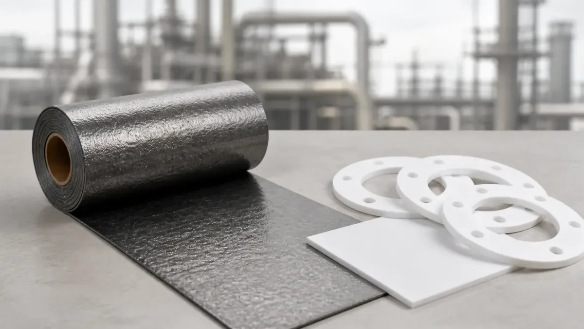
Flexible graphite and PTFE solve different sealing problems. PTFE brings broad chemical resistance and clean handling in many low-to-moderate-temperature services. Flexible graphite brings high-temperature capability, conformability and useful load-retention characteristics when the exact construction is compatible with the medium. Neither material family can be selected from its name alone.
The comparison must use the installed gasket system, not only raw sheet. Virgin PTFE, filled PTFE, modified PTFE and expanded PTFE do not creep or seal in the same way. Plain flexible graphite sheet, mechanically reinforced graphite and graphite-filled engineered gaskets also have different pressure, handling and oxidation limits. The correct question is therefore: which named construction is defensible for this service, this flange, this available load and this qualification requirement?
A classic NIST paper measured calorimetric properties of PTFE powder and moulded material from 0 to 365 K and noted historical gasket and packing use; see the NIST report on PTFE thermodynamic properties. That paper is useful for thermal-property background, but it is not a gasket compatibility chart and does not establish pressure, creep, leak or chemical-service limits for a specific PTFE gasket.
Neither Material Wins Everywhere
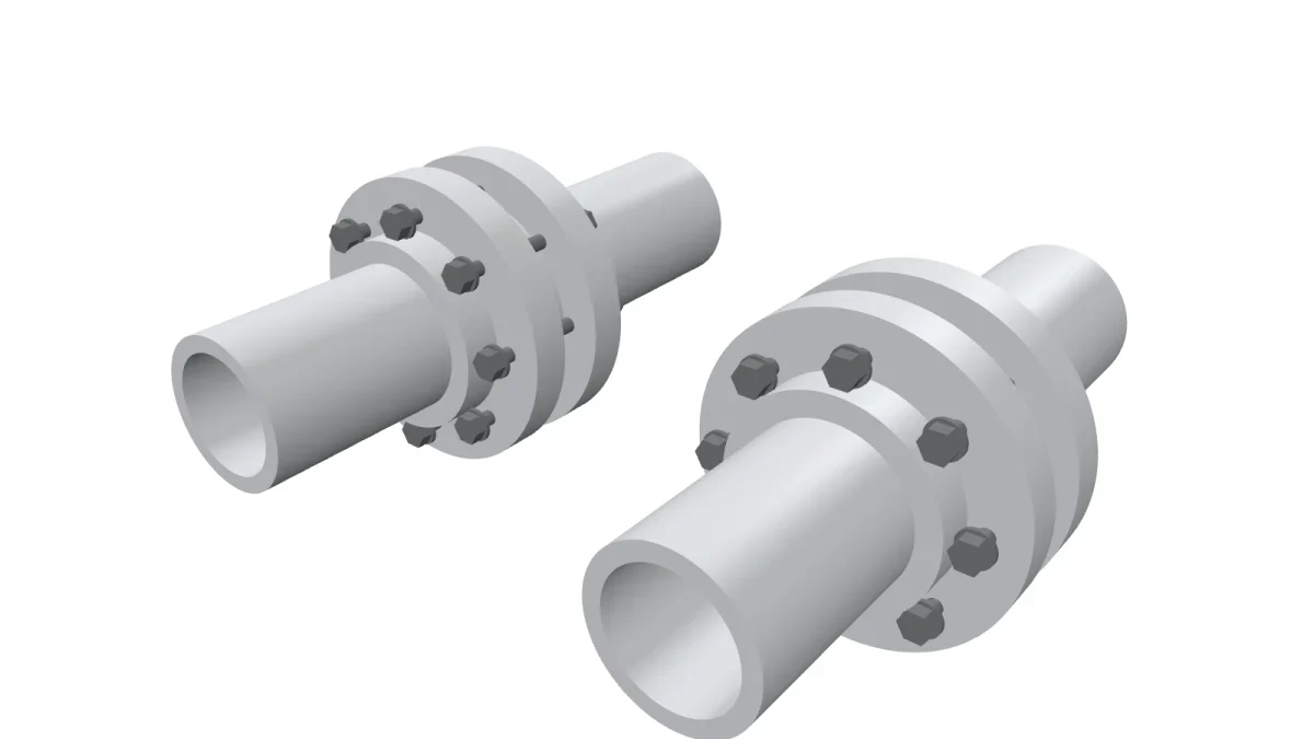
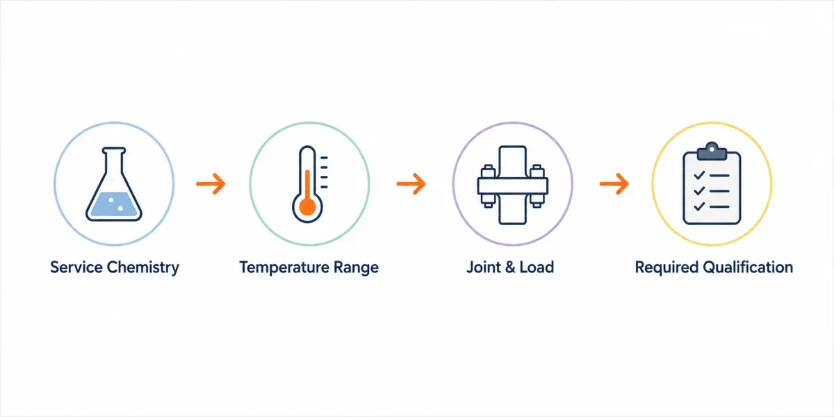
Material neutrality is not the goal; a defensible choice is. The decision starts with four inputs: complete service chemistry, continuous and excursion temperature, the joint and available load, and the qualification or certification that the equipment requires. Once those inputs are complete, the candidate construction can be checked against a product data sheet, compatibility table, pressure-temperature envelope and plant-approved assembly procedure.
The flange construction often narrows the choice before chemistry does. A rigid metallic flange with adequate and controllable gasket stress can use a different range of PTFE constructions from a glass-lined, plastic or damaged flange that develops low or uneven compressive load. The same is true for graphite: plain foil may be too fragile for handling, while a reinforced construction may add strength but also introduces an insert metal whose corrosion and temperature limits must be checked.
The first table is therefore not a universal selection chart. It is a screening matrix that tells the buyer, engineer and supplier what must be known before either material can be approved.
| Service-screening field | PTFE candidate questions | Flexible-graphite candidate questions | Approval evidence |
|---|---|---|---|
| Complete medium | Is the PTFE virgin, filled, modified or expanded, and is that formulation compatible with every chemical component and cleaning fluid? | Is carbon compatible with the medium, and is the reinforcement, coating or insert metal compatible with the full composition? | Product-specific compatibility data plus plant review of concentration, contaminants, cleaning and upset conditions |
| Temperature profile | What continuous, excursion and low-temperature limits apply to the named PTFE construction under load? | Is the service in air, steam, inert gas or another atmosphere, and does oxidation or the insert metal control the limit? | Pressure-temperature chart or manufacturer data for the exact thickness and construction |
| Joint and available load | Can the flange provide the required seating stress without damaging the facing, and is creep relaxation acceptable? | Does the joint provide even seating, adequate anti-extrusion support and suitable handling strength? | Flange standard, facing, dimensions, bolt data, assembly procedure and calculation or approved design method |
| Required qualification | Does the product need oxygen-service cleaning, food or pharmaceutical documentation, emissions evidence or cryogenic qualification? | Does the complete gasket or joint require fire-test, emissions, oxidation or service-specific evidence? | Applicable certificate, test standard, lot traceability and scope of approval |
| Maintenance and availability | Is the required formulation, thickness and cut form available within the outage window? | Is plain, reinforced or engineered graphite available with the specified insert and dimensions? | Current quotation, lead time, approved vendor list and installation history |
Steam and High Temperature
Steam exposes PTFE temperature and creep limits together. Some PTFE gasket products publish broad temperature ranges, but those headline limits do not by themselves approve a thickness, pressure or joint. Continuous gasket service may be controlled by creep relaxation, flange load, pressure cycling or the product’s own pressure-temperature chart before the polymer reaches a headline temperature limit.
Flexible graphite is often the stronger candidate for hot steam when chemical compatibility allows, but the selection still belongs to a named construction. Plain foil, tanged-metal reinforced sheet, eyeleted gaskets and spiral-wound designs do not have one common pressure-temperature envelope. The high-temperature graphite gasket article explains the material-selection criteria, while final approval must follow the selected product data, flange design and assembly procedure.
A steam case should therefore be written as an RFQ rather than as a fixed threshold: state operating and test pressure, continuous and excursion temperature, steam condition, startup frequency, water-hammer risk, shutdown vacuum, flange standard, facing, gasket dimensions, bolt material and available load. Only then can the supplier and engineer compare a PTFE construction with a graphite construction.
Thermal cycling matters because the flange, bolts and gasket move differently as the line heats and cools. PTFE may lose load through creep, while a graphite construction may face oxidation, extrusion or reinforcement limits. The joint record should capture startup leaks, retorque policy and removed-gasket condition instead of assuming that one material always retains load better in every joint.
Strong Acids and Oxidizers
Strong acids are not one category. Hydrochloric acid, nitric acid, sulfuric acid, mixed acids and oxidizing cleaning solutions can affect carbon, PTFE fillers, insert metals and flange materials differently. A useful compatibility review therefore records the complete mixture, concentration range, temperature, contaminants, cleaning cycle and abnormal conditions rather than selecting from the acid name alone.
Flexible-graphite product guidance commonly warns against concentrated strong oxidizing media. That warning applies to carbon, while the complete gasket may introduce additional restrictions from stainless steel, nickel alloy or other reinforcement. PTFE has broad chemical resistance, but the exact formulation still matters: filled, modified and expanded PTFE products are not automatically interchangeable, and highly reactive fluorinating agents or other exceptional media require specialist review.
The industrial sealing solution page keeps gasket forms separate, but it does not replace product-specific compatibility evidence. When the medium oxidizes carbon, PTFE may be the better starting option; when temperature or load retention controls the joint, graphite may be the better starting option. Neither statement is a release decision until the exact construction and full service have been checked.
Cleaning chemistry is part of service chemistry. A process line may run a mild medium during production and a more aggressive wash during shutdown. The cleaning stage can control the gasket selection even when it occupies only a small portion of the operating cycle.
Cryogenic and Low Temperature
PTFE has a long history in low-temperature seals, but cryogenic qualification must be tied to the gasket product and the complete assembly. Specific PTFE gasket grades publish very low minimum temperatures; for example, Garlock lists a specific GYLON PTFE construction down to approximately -268 °C. That product-specific temperature statement does not by itself prove suitability for a particular pressure, oxygen-service cleanliness requirement or flange design.
Flexible graphite also remains a carbon material at low temperature, but a plain graphite gasket may not be the first choice for a small clean cryogenic line. PTFE can offer a clean surface and broad inertness, while graphite or a composite system may be selected in larger hydrocarbon equipment where fire exposure, flange size or plant standard changes the requirement. Liquid nitrogen, liquid oxygen and liquid hydrogen must not be treated as one generic cryogenic service because cleanliness, permeability, ignition and qualification requirements differ.
Cryogenic contraction can loosen a joint even when the gasket material remains flexible. The flange, bolts and gasket contract by different amounts, and temperature gradients can distort the joint. A qualification plan should therefore record assembly temperature, cooldown rate, pressure steps, leak-measurement method and warm-up inspection.
Cryogenic service qualification must rest on a tested construction. A room-temperature datasheet alone does not establish suitability for cryogenic service. Friction and wear data for PTFE-based solid-lubricant composites in liquid nitrogen do not directly establish static-gasket performance.
Creep and Bolt Load Retention
Creep relaxation is an important mechanical distinction, but it has to be measured for the actual gasket. PTFE formulations, thicknesses and manufacturing routes vary widely, and graphite constructions vary in density, reinforcement and facing. The correct comparison is not “PTFE versus graphite” as two single values; it is one named PTFE construction versus one named graphite construction under the same controlled test conditions.
The official ASTM F38 creep-relaxation method provides ways to measure loss after compressive stress is applied, while the ASTM F37 sealability methods cover leakage testing under defined conditions. Neither method creates a universal pass value. Results depend on specimen thickness, stress, time, temperature, fluid, fixture and measurement method, and the plant still has to correlate laboratory data with the actual joint.
| Test-plan field | Required definition | Why it changes the result | Record for comparison |
|---|---|---|---|
| Material identity | Manufacturer, grade, formulation, reinforcement, thickness, density and lot | Different PTFE fillers and graphite reinforcements change deformation and leakage behaviour | Complete specimen identification and certificate reference |
| Loading condition | Initial stress or bolt load, loading method, fixture and surface condition | Creep and leakage can change substantially with seating stress and facing | Initial thickness, load and calibration data |
| Time and temperature | Hold duration, temperature profile, thermal cycles and cooling condition | Relaxation and recovery are time- and temperature-dependent | Load or thickness at each approved checkpoint |
| Sealability method | Test fluid, pressure, fixture, leak instrument and stabilization period | A leak value is not comparable when fluid, pressure or instrument changes | Measured leakage with units, uncertainty and test conditions |
| Acceptance and correlation | Project pass criteria, service risk and how the result maps to the actual flange | Laboratory ranking is not automatically a plant release decision | Approval authority, deviations and field follow-up plan |
Fire Safety
Fire safety separates material behaviour from assembly qualification. Flexible graphite does not melt in the same way as PTFE and is commonly used in gasket systems intended for severe heat exposure. PTFE can lose volume or decompose under fire conditions. Those material differences explain why graphite appears frequently in fire-tested systems, but they do not make every graphite gasket automatically fire-safe.
The API standards plan identifies API 6FB as the fire-test standard for end connections, while API 6FA addresses fire testing of valves. The test applies to the specified connection or valve assembly, including gasket construction, flange or body, bolts, pressure and cooling sequence. A claim must therefore name the applicable standard, edition, tested configuration and certificate scope.
The transition from older asbestos gaskets also brings installation and fire questions. The asbestos-to-graphite replacement article explains the change in bolt load and flange contact, while the graphite sealing article for valves and flanges separates static gaskets from packing and other sealing forms.
For a defined fire requirement, selection should be based on the tested gasket or assembly. The material name alone does not establish fire performance. Fire performance belongs to the tested assembly because bolts, flanges, valve bodies and gasket layers heat and cool at different rates.
Cost and Availability
PTFE sheet is available in virgin, expanded, modified and filled forms. Flexible graphite is available as plain roll or sheet, mechanically reinforced sheet, eyeleted cut gaskets and filler in engineered gasket systems. The least expensive raw sheet is not necessarily the lowest installed cost, but an article cannot responsibly pre-fill prices, service life or maintenance frequency for every plant.
Compare total cost using the buyer’s quotation and maintenance records. The input model should include gasket price, conversion, reinforcement, installation labour, retorque or inspection labour, outage frequency, leak consequence, inventory and lead time. Each value should have a source date and service class so that the comparison remains auditable.
| Total-cost input | PTFE candidate | Graphite candidate | Evidence source |
|---|---|---|---|
| Material and conversion price | Enter quoted grade, thickness, cut form and quantity | Enter quoted construction, reinforcement, cut form and quantity | Current supplier quotation |
| Installation and inspection labour | Enter actual site time and required inspection steps | Enter actual site time and required inspection steps | Work-order history or trial record |
| Maintenance frequency | Enter verified inspection, retorque and replacement frequency for the same service class | Enter verified inspection, retorque and replacement frequency for the same service class | Plant maintenance history |
| Outage and leak consequence | Enter approved cost or risk value for the joint | Enter approved cost or risk value for the joint | Plant finance and risk assessment |
| Availability and inventory | Lead time, minimum order and local stock requirement | Lead time, minimum order and reinforcement-specific stock requirement | Supplier confirmation and inventory policy |
Packing and documentation also affect supply. The graphite packaging article and export documentation guide show why sheet form, batch identity, reinforcement and certificate wording must be stated before shipment.
How to Build a Comparison Package
A defensible comparison package uses the same fields for both candidates. Start with a one-page joint record: equipment tag, flange standard, facing, nominal pipe size, gasket dimensions, bolt material, lubricant, tightening method, operating pressure, test pressure, continuous temperature, excursion temperature, startup frequency and complete medium composition. Have a photo or drawing ready for follow-up when surface damage, narrow seating width or a special flange arrangement may affect the result; after the initial inquiry, send it by email or another agreed secure channel.
Next, identify the exact product construction. For PTFE, record whether the gasket is virgin, filled, modified, expanded, microcellular or an envelope design. Name the filler and any carrier or insert because those details can change compressibility, cold flow, chemical resistance and cleanliness. For graphite, state whether the item is plain foil, laminated sheet, tanged-metal reinforced, foil-insert reinforced, eyeleted or part of a spiral-wound or other engineered gasket. Record graphite density, reinforcement alloy, coating and edge condition where the specification uses them.
Then separate four types of evidence. A manufacturer data sheet establishes the supplier’s published range for the named product. A test report establishes performance for a defined specimen and method. A certificate establishes lot identity or composition. A plant qualification record establishes whether the joint worked under the approved service and assembly procedure. These documents are related, but one cannot replace the others. A carbon-content certificate does not prove leak tightness, and a laboratory sealability result does not approve an unreviewed flange.
Use a deviation log whenever the quotation differs from the approved construction. A change in PTFE filler, graphite density, reinforcement alloy, thickness, manufacturer or production route may require technical review even when the purchase description still says “PTFE gasket” or “graphite gasket.” The log should identify the requested item, proposed substitute, affected performance fields, evidence reviewed, approval authority and effective date. This protects purchasing from accepting a visually similar but technically different product.
Installation evidence also belongs in the comparison. Record gasket centring, flange cleanliness, hardware condition, lubricant, pass sequence, final load method and any approved retorque. When the joint fails, those records help separate a material-selection problem from uneven assembly, damaged facing, insufficient load or process upset. Without installation data, replacing graphite with PTFE—or PTFE with graphite—may only move the same underlying problem to a different material.
Finally, define the expansion rule. A construction approved on one line may be extended only to joints that share the service chemistry, temperature range, flange family, load capability and qualification requirement stated in the approval. A different cleaning cycle, lower-load flange, fire-test requirement or oxygen-service rule creates a new review. This prevents a successful local trial from becoming an uncontrolled plant-wide material standard.
A Decision You Can Defend to Engineering
A decision that engineering can defend contains the complete medium and concentration range, continuous and excursion temperature, operating and test pressure, flange standard and facing, gasket dimensions, available gasket stress, required qualification, maintenance constraints and the exact candidate construction. That information is more useful than a generic statement that graphite is for heat and PTFE is for chemicals.
Write the decision as a short conditional engineering statement. For example: select the named reinforced graphite construction only after its pressure-temperature envelope, insert compatibility and joint load are approved; or select the named PTFE construction only after its formulation, creep behaviour, low-temperature or chemical qualification and flange load are approved. The written decision should state both the reason for selection and the condition that would invalidate it.
Keep material identity separate from construction identity. “Graphite gasket” does not tell engineering whether the item is plain foil, mechanically reinforced sheet or an engineered gasket with graphite filler. “PTFE gasket” does not identify virgin, filled, modified or expanded PTFE. The purchase description must name the construction that was actually reviewed.
QDZRT Graphite supplies flexible graphite sheet and related graphite sealing materials for defined industrial services. Adjacent forms can be reviewed in the graphite products range and graphite paper page, while the project communication guidance explains how to organize drawings, service data and approvals.
Start the inquiry through the contact page with the complete service data. After we reply, send the controlled flange drawing by email or another agreed secure channel. The discussion should state where graphite is the supported option and identify where PTFE or another gasket system is more appropriate.