Replacing asbestos-containing gasket material is not a same-thickness material swap. The new flexible graphite sheet compresses differently, conforms to the flange differently and retains bolt load differently. The old joint may have been maintained around the behaviour of a fibre-and-binder gasket for years. When the material changes, installation and qualification must change with it.
The safety reason for substitution is clear. The U.S. Environmental Protection Agency describes asbestos as a mineral fibre and outlines serious exposure concerns; see the EPA asbestos information. OSHA also regulates removal of asbestos-containing gaskets and provides interpretation letters for specific work scenarios; see the OSHA interpretation on asbestos gasket removal. In practice, the removal category, controls and waste handling depend on the material condition, the work method and the jurisdiction. A new non-asbestos gasket does not make removal of the old one an ordinary maintenance task.
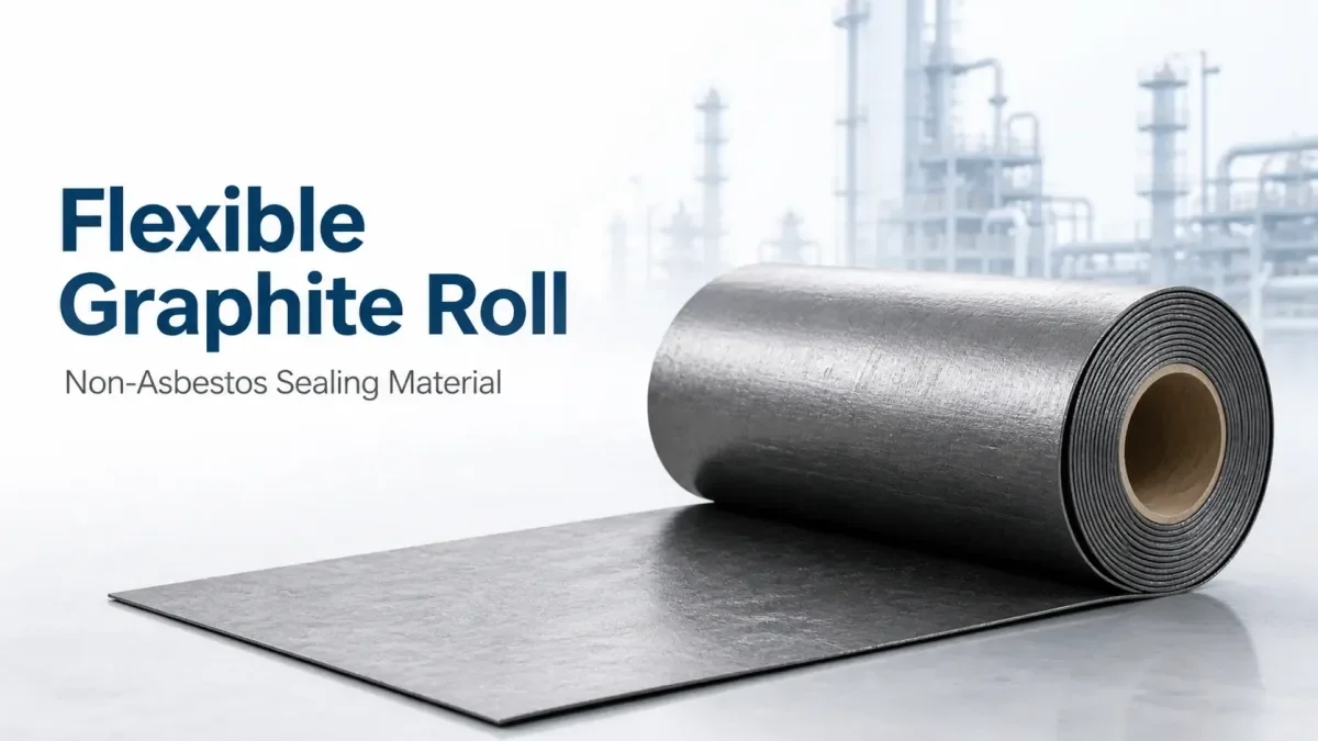
Once a plant has decided to replace the material, the important questions move to the flange: joint condition, graphite construction, bolt loading, installation and qualification. QDZRT Graphite supplies graphite sealing materials in sheet, roll and reinforced forms; the equipment owner and gasket engineer define the joint design, regulatory requirements and plant qualification.
Why the Substitution Happened
The substitution happened because asbestos fibres create health and compliance burdens across manufacturing, installation, maintenance and disposal. Supply chains also increasingly require an asbestos-free declaration. That pressure removes a legacy material even when the old gasket seemed familiar to maintenance crews.
Performance also changed the direction. Fibre-and-binder gaskets can harden, shrink or lose binder after repeated heat exposure. Many flexible-graphite constructions respond differently: plain graphite foil behaves differently from reinforced graphite, and both differ from a fibre sheet that relies on an elastomeric binder system. The comparison therefore has to be construction-specific rather than material-name specific.
The plant therefore needs a controlled change, not a purchasing substitution. The change package must identify the old gasket type, thickness, flange standard, service medium, bolt procedure, leak history and the proposed graphite construction. A controlled replacement usually moves through four steps: record the legacy gasket, review the flange and bolts, choose the graphite construction, and qualify the change on one representative line.
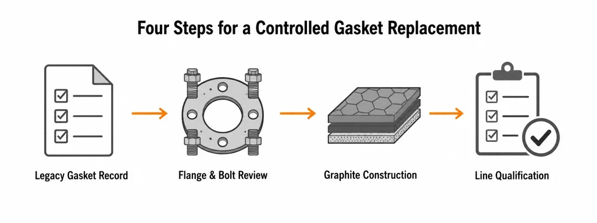
Familiar does not mean equivalent, and similarity is not qualification. The right replacement may still be graphite, but it has to be the specific graphite construction whose density, reinforcement, facing condition and load behaviour match the joint.
Begin with a line survey. Record gasket manufacturer or legacy description, nominal thickness, flange standard, service medium, continuous temperature, pressure class, installation date and the last three maintenance events. Separate joints that leak after thermal cycling from joints that leak immediately after start-up. The first pattern points toward load retention, flange movement or oxidation. The second pattern points more often toward surface condition, gasket selection or installation control.
| Change-control topic | What to record from the legacy joint | What to confirm for the graphite candidate | Why approval may differ by line |
|---|---|---|---|
| Nominal thickness and geometry | Legacy thickness, gasket width, inner/outer diameters, facing type and any compressed witness marks | Named graphite construction, reinforcement type and the proposed thickness for that exact joint | Thickness cannot be copied automatically because contact area, bolt load and flange condition may have changed over years of service |
| Compressibility and recovery | Any available legacy material data, failure history and installation notes | Construction-specific compressibility and recovery values from the approved data sheet or ASTM F36 method | Fibre sheet, plain graphite foil and reinforced graphite do not seat and unload in the same way |
| Service medium and exclusions | Complete medium composition, concentration, contamination, pressure, temperature and upset conditions | Compatibility guidance for the complete graphite construction, including insert metal and any coating or treatment | A material that works in hydrocarbon or steam service may not be acceptable in a strong oxidizing acid or where graphite particles are prohibited |
| Bolt-load control | Joint size, bolt count, bolt material, lubricant practice, tightening record and any retorque history | Approved assembly procedure fields: target stress or torque, pass sequence, lubricant and any retorque decision | The correct load window comes from the joint design and assembly procedure, not from a universal graphite rule |
| Qualification evidence | Leak history, maintenance interval, removed-gasket condition and shutdown findings | One-line trial plan, leak-measurement method, inspection points and release authority | A plant can approve one service class first and expand only after the same evidence is repeated where conditions differ |
What Changes at the Flange Face
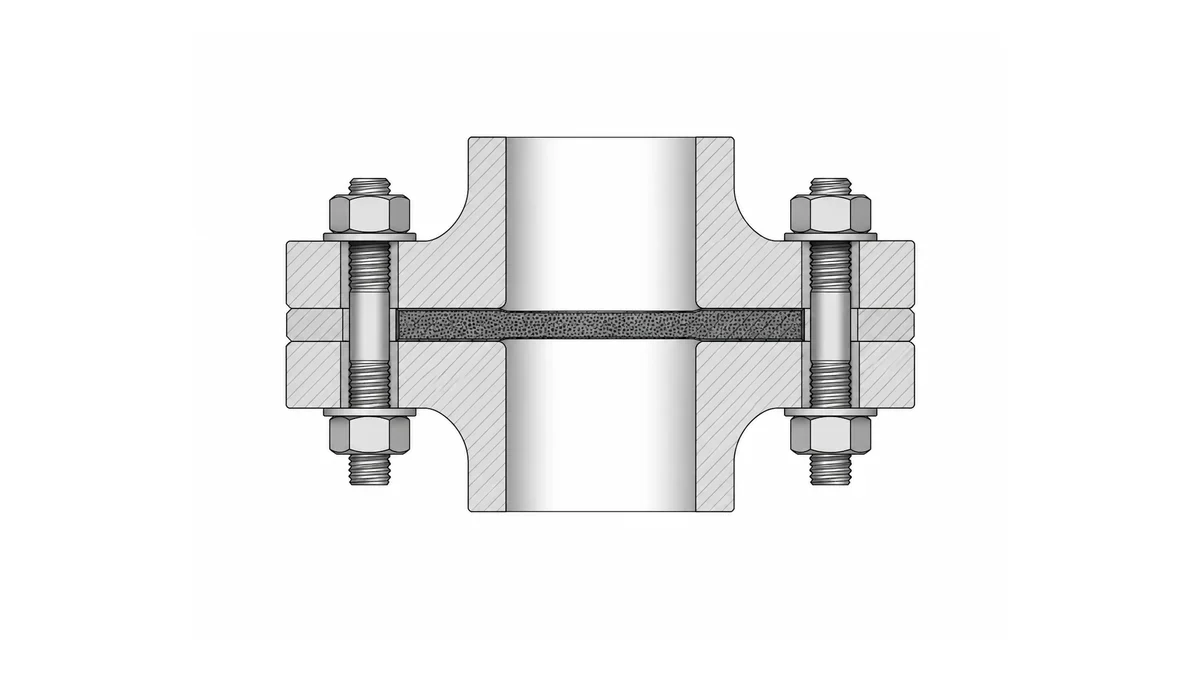
At the flange face, flexible graphite follows machining marks and minor scratches more readily than a hard aged fibre gasket. That can improve initial contact, but it also means the flange surface becomes part of the selected construction. A softer material does not repair a damaged flange; it only changes how the damage appears in service.
Clean the flange without dry grinding asbestos residue into the air. The removal plan follows the applicable asbestos controls. Once the old gasket is removed, inspect both faces, bolt holes and any raised-face or tongue-and-groove features. Look for pitting, radial scratches, corrosion under the old gasket and signs that the previous material was masking poor parallelism.
The new gasket width may need adjustment. A legacy gasket sometimes spread into a damaged area and still appeared acceptable because the old material was thicker or stiffer. A reinforced graphite gasket may seat differently and concentrate load in a different effective area. Any thickness or width change therefore has to be checked against effective gasket area, flange rotation and available bolt load.
Surface inspection does need records, but the record belongs to the approved maintenance standard. Use the site procedure to define measurement locations, straightedge checks, facing finish and acceptance limits. Example observations are useful for discussion, but they do not replace the plant’s own flange-repair or replacement criteria.
Bolt Load and Retorquing
Bolt load is where many direct swaps fail. Flexible graphite can seat differently from a fibre gasket, and load retention must be judged for the actual construction, bolt set and flange geometry. A plant should calculate or otherwise establish the target bolt stress or torque from the approved joint procedure rather than assume that a new graphite gasket will tolerate the old routine.
Calculate average gasket stress from effective gasket area and total bolt load within the joint-design method being used. The calculation checks whether the joint is operating in a reasonable seating window. If load scatter is high, first review the assembly method, lubrication, bolt condition and flange alignment before changing the gasket material again.
Reinforced graphite improves handling and often improves blowout resistance, but insert type does not remove the need for even load. The valve, pump and flange sealing article separates plain sheet, packing and joint-specific sealing duties so that one form is not transferred blindly into another.
Retorquing practice also changes. Some fibre gaskets needed repeated tightening as binder relaxed. A graphite replacement may retain load differently, but the joint, bolt material, medium and safety conditions still control whether any retorque is allowed. Hot retorquing can be unsafe on pressurized or hazardous service and should never be improvised at the flange.
More torque is not a repair method. A retorque decision is made before start-up, not while the joint is hot. Define whether the line will be depressurized, the temperature window, the tool, the permitted correction and the stop conditions. Retorque data belongs to the joint record because it becomes part of the evidence for later replacements.
| Assembly-procedure field | What the site procedure should state | Why it matters after a graphite substitution | What to record |
|---|---|---|---|
| Target load basis | Target bolt stress or torque, the basis used to derive it and the permitted tool method | A new gasket construction may require a different seating window or verification method | Joint ID, gasket construction, calculated target and revision status of the procedure |
| Lubrication and hardware condition | Approved lubricant, stud condition, nut condition and replacement rules | Scatter in bolt friction can overwhelm any theoretical material advantage | Lubricant used, replaced hardware and any hardware abnormalities |
| Pass sequence | Cross pattern, number of passes and whether a circular verification pass is required | The sequence controls load distribution and seating uniformity across the graphite gasket | Actual pass completion, any skipped hardware and the final verification status |
| Retorque decision | Whether any cold or shutdown retorque is allowed, under what safety conditions and who may authorize it | Retorque policy must be joint-specific and risk-based, not a universal graphite rule | Retorque authorization, measured results and reason for the intervention |
| Inspection and release | Who verifies leak status, which leakage method applies and when post-startup inspection is required | The release method must reflect medium hazard, emission class and maintenance history | Startup outcome, leak observations and any follow-up action |
Temperature and Oxidation Limits Are Different
The old asbestos gasket may have been described by one temperature headline, but its binder and reinforcement controlled the real service envelope. Flexible graphite also has separate limits. In open air, oxidation can become the controlling factor. In inert gas or vacuum, a graphite-based sealing element may tolerate much higher temperature, but the complete construction still includes reinforcement, facing condition, edge exposure and equipment constraints.
Steam at one temperature, thermal oil at another and furnace gas at a third are not one generic “high-temperature” category. The high-temperature graphite gasket article is useful as a route overview, but the final limit still belongs to the named construction in the approved service environment.
The comparison with PTFE gasket material also shifts after substitution. PTFE may remain preferable for some strong oxidizers at moderate temperature, while graphite often offers a better fit for hot hydrocarbon, steam or furnace-related duties. That comparison only remains valid when the medium, concentration and temperature are all stated explicitly.
Oxidation and binder ageing are different limits. Published graphite-foil data often compares mass loss or stability for named products in air over defined time windows, while fibre-sheet data may focus more heavily on binder-dependent temperature resistance. The lesson for replacement work is simple: state the complete gasket construction and the tested atmosphere before adopting any temperature line from a catalogue or a past job.
| Service-screening area | What must be verified | Typical risk if it is not checked | Preferred evidence |
|---|---|---|---|
| Open-air hot service | Continuous and short-duration temperature, oxygen access, edge exposure and shutdown pattern | Edge oxidation, mass loss and reduced sealing life | Named product data or plant test evidence for the complete gasket construction in air |
| Steam and hydrocarbon service | Full medium description, pressure, startup pattern and emission requirement | A material selected only on temperature may miss leak-tightness, creep or fire-safe requirements | Approved compatibility data and joint qualification record |
| Strong oxidizers and special chemicals | Chemical identity, concentration, contamination, cleaning chemicals and upset composition | Carbon attack or incompatibility of the reinforcement or treatment layer | Product-specific compatibility guidance and the plant’s own chemical review |
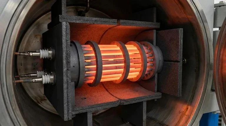
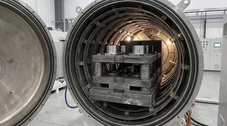
| Vacuum or inert-gas furnace duty | True atmosphere, air-ingress risk, flange movement and the complete construction including inserts | Assuming “graphite” alone defines the limit when the insert metal or ingress event is actually controlling | Equipment-specific approval and service-history evidence |
| Non-temperature exclusions | Need for electrical isolation, particle restrictions, dynamic motion or large unsupported gaps | A technically compatible graphite sheet is approved for a duty it was never meant to perform | Joint design review and the exclusion list in the change package |
Where Graphite Is Not a Direct Swap
Graphite is not a direct swap where strong oxidizers attack carbon, where graphite particles cannot be tolerated, where the flange has a large unsupported extrusion gap, or where a soft conductive gasket creates a different equipment risk. Those exclusions should be written before the first installation rather than discovered after the first failure.
Dynamic sealing is another boundary. Valve-stem packing and pump-shaft packing use graphite in moving interfaces, but a cut flange gasket cannot be transferred into those positions. The same caution applies when people compare graphite paper, plain foil, tanged inserts, eyeleted designs and die-cut parts as if they were one interchangeable material family.
Electrical continuity and galvanic interaction can matter on some equipment. Graphite is conductive. A joint that requires electrical isolation needs an insulating gasket system, not simply a graphite sheet of a different thickness. Likewise, where metallic contamination or particle release is tightly controlled, the plant may need a different sealing route altogether.
A safe substitution list includes explicit exclusions. For example, a chlorine-dioxide line may be better served by a compatible fluoropolymer-based sealing system because the medium is strongly oxidizing. A large damaged steel flange may need a controlled repair or a different gasket family before any graphite option is considered. A furnace line that cycles into air ingress may need additional oxidation evidence instead of a direct material transfer.
A controlled substitution states where it stops, who approves expansion and which evidence must be repeated on a different service class. Exclusions make the replacement plan credible because they show the team understands the boundary between “graphite can work” and “this line is actually qualified.”
Qualifying the Replacement on One Line First
Qualify one representative line before changing an entire plant. Select a joint with known service, accessible inspection and a history that can be compared. Record the old gasket, the new graphite construction, the flange condition, the bolt procedure, the expected startup sequence and the leak-measurement method before installation begins.
The trial plan should define representative joints, the batch identity of the trial gaskets, the startup and shutdown conditions, the inspection points and the people who can release the result. The number of joints, cycles, inspections and hold periods should be set by service risk and practicality. They should not be copied from a generic article into a formal plant standard without review.
Write the trial acceptance before installation. A realistic acceptance plan states the leak-measurement method, the operating window, the post-startup inspection timing, the shutdown inspection scope and the failure criteria. For a hazardous service, the leakage method and threshold may be much tighter than for a low-risk utility line. The qualification therefore belongs to the plant’s approved plan, not to an invented universal number.
After shutdown, examine compression, adhesion, oxidation marks, leak path evidence and any abnormal hardware condition. Compare those findings with the installation record and startup record. If the trial passes, expand first to similar joints with the same service class, flange arrangement and assembly controls. A plant-wide replacement based on one success without similarity review is still a shortcut.
The result can be communicated with the project communication article. One line produces evidence. That evidence should stay with the batch record, the joint ID and the installation procedure so the next replacement is repeatable rather than anecdotal.
Documentation the Plant Will Ask For
The plant will ask for an asbestos-free declaration, material description, certificate of analysis, safety data sheet, batch traceability, dimensions, density, carbon content and insert material if the graphite is reinforced. If the service is regulated, it may also ask for a statement of applicable exclusions, compatible media notes and the qualification status of that construction.
The change-control file includes the old and new material comparison, flange list, service conditions, installation procedure, risk review, qualification results, maintenance instructions and the approval authority. Documentation also controls substitution across purchasing cycles. The approved material code should not be only “graphite gasket.” It can include construction, nominal thickness, insert type, facing dimensions and the related qualification file.
Maintenance instructions change too. A flexible graphite gasket may adhere to the flange, but the removal method must avoid gouging the facing. Record whether anti-stick treatment is permitted, whether reinforcement changed cutting behaviour and whether the line requires a preserved used sample for later failure review.
Commercial documents must use the same product description as labels and certificates. The graphite export documentation guide and packaging and logistics article cover shipment consistency. Internally, the plant also needs its own material code, revision status and approval boundary to stay aligned with the purchase order and store issue records.
The first order should be large enough to qualify cutting, installation and one spare set, but small enough that a failed trial does not strand plant-wide inventory. Review the graphite product range or use the contact page to start the discussion for a defined replacement line. Include the old gasket construction, service data and qualification quantity in the inquiry; after we reply, send the controlled flange drawing by email or another agreed secure channel so that the quotation stays tied to the actual change package.