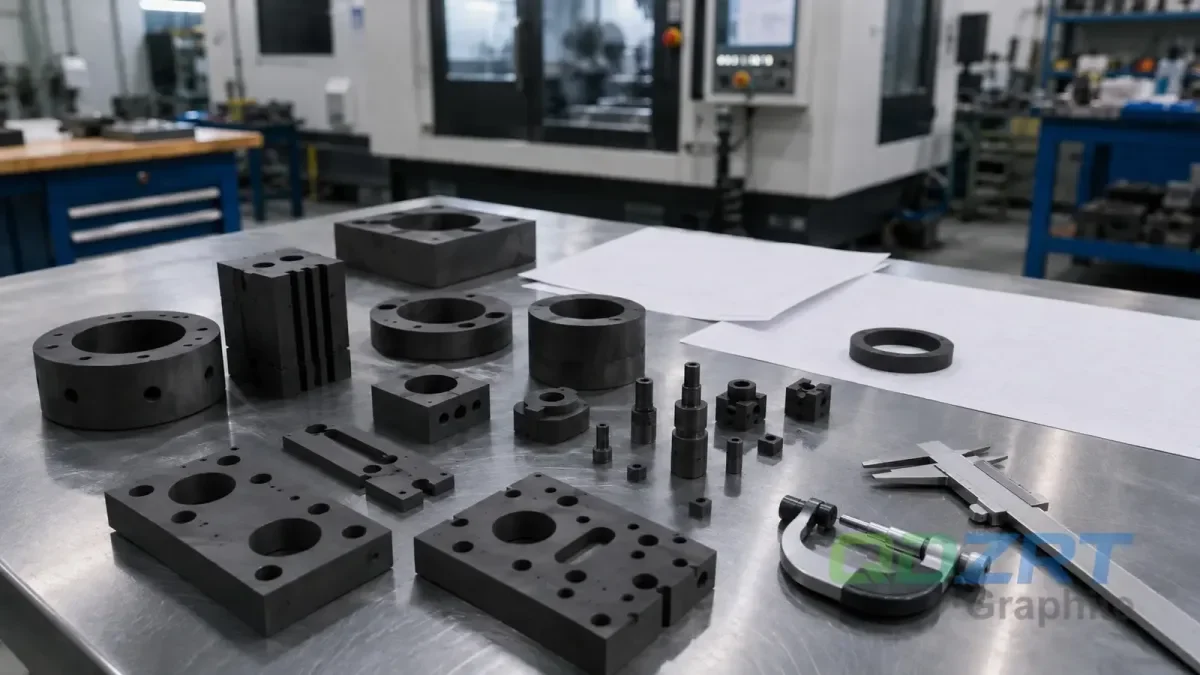
Custom graphite machining needs a controlled file set, not just a product name, photograph, or unapproved drawing. Even an apparently complete drawing can leave uncertainty about assembly-critical dimensions, position or flatness references, support for a narrow wall, and the measurement method; those gaps affect grade selection, blank allowance, setup count, tool access, inspection time, scrap exposure, packing design, and quotation.
Before ordering rings, plates, molds, bushings, fixtures, electrodes, or furnace components, make the controlling geometry, material, and inspection requirements clear enough to quote. The values below are review starting points; approved project documents set the final requirements.
1. Identify the Controlling Product Definition
The RFQ must state which product-definition source governs the order. In a conventional drawing-based project, the approved 2D drawing may contain dimensions, tolerances, datums, notes, material requirements, surface requirements, and revision history. In a model-based definition project, an annotated 3D model may carry product manufacturing information. Some projects deliberately use both: the model controls geometry while the drawing controls selected notes, inspection characteristics, or contractual information.
The buyer and supplier should not assume that one source always overrides another. The order file should identify the approved 2D revision, approved 3D revision, units, part number, applicable specification references, and the rule used when files conflict. ASME Y14.5 provides the language for dimensions and geometric tolerances on engineering drawings and digital models, while ASME Y14.41 addresses digital product-definition data practices. These standards support a defined product definition; they do not select the graphite grade or guarantee a machining result.
| Controlled input | What the RFQ should identify | Reason for control |
|---|---|---|
| Product-definition authority | Approved 2D drawing, annotated 3D model, or a defined combination | Prevents quotation, machining, and inspection from using different geometry or tolerance sources. |
| Revision and status | Revision code, release date, approval status, and obsolete files to ignore | Stops an earlier drawing or model from silently returning to the project. |
| Units and scale | Millimetres or inches; do not rely on visual scale | Avoids conversion and interpretation errors. |
| Conflict rule | Which source governs geometry, notes, material, inspection, and acceptance when files differ | Creates one decision path before work begins. |
| Physical sample | New, used, worn, chipped, coated, modified, or reference-only condition | A worn sample may not represent the original design dimensions. |
| Change owner | Named buyer and our team contacts authorised to approve clarifications | Prevents informal messages from creating a second uncontrolled definition. |
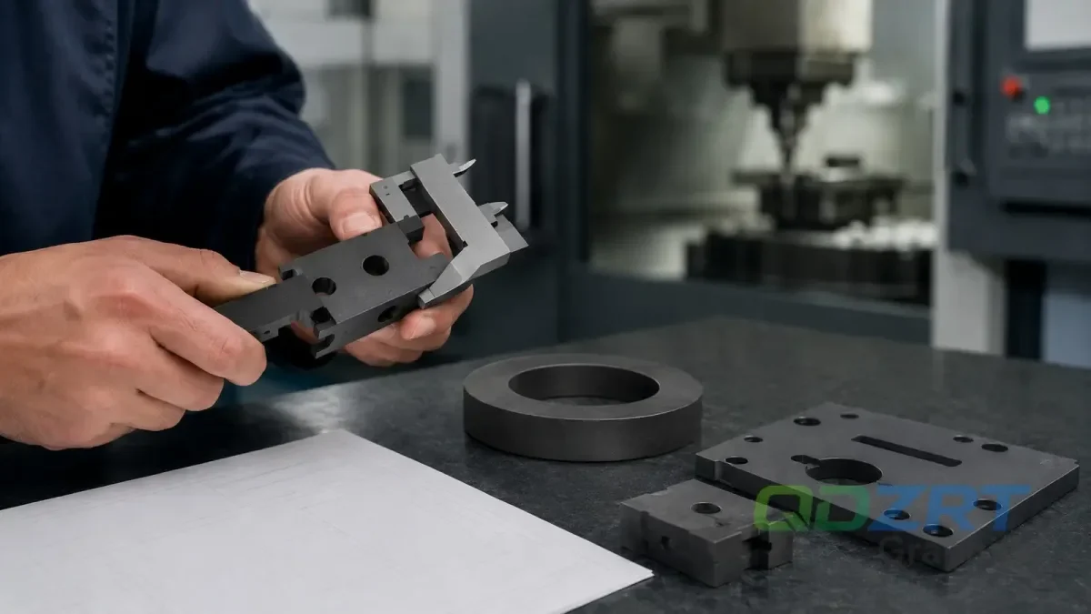
A physical sample can supplement the defined product information, but it should not be treated as an unquestioned master. The buyer should state whether wear, oxidation, coating loss, breakage, repair, or dimensional distortion may be present. Copying a used sample without this context can reproduce damage rather than the intended design. The related graphite drawing-review article explains how datums, holes, walls, and edge risk interact during DFM review.
2. Separate Functional Features From General Geometry
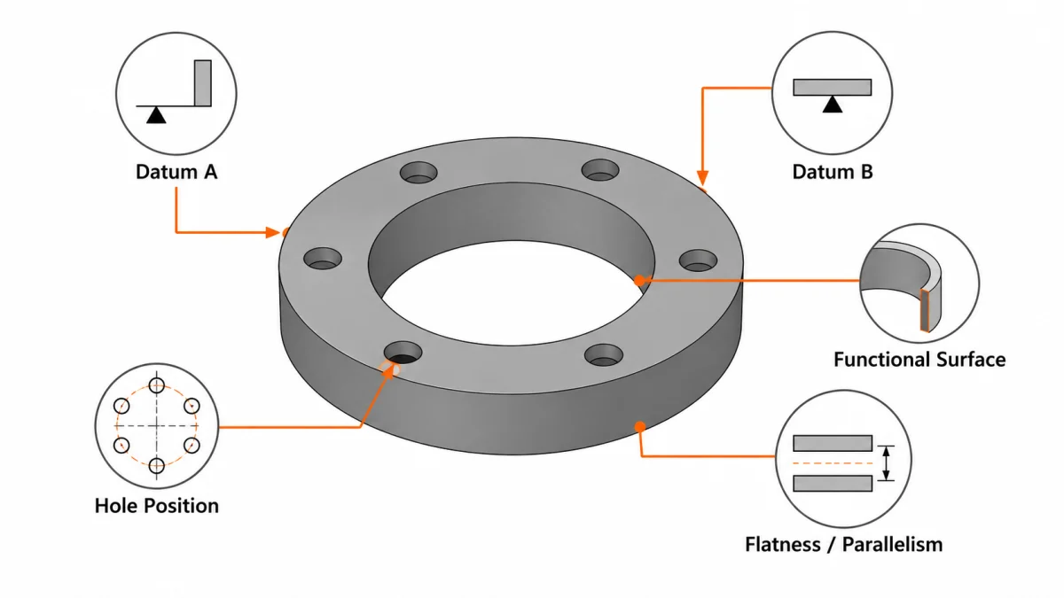
Not every dimension deserves the same machining and inspection effort. Functional features may control assembly, sealing, location, electrical contact, thermal contact, rotation, sliding, or alignment. General outline dimensions may only define clearance or stock shape. Applying the narrowest tolerance to every dimension can increase setup, inspection, and scrap exposure without improving the part’s function.
The buyer should identify which dimensions affect fit or performance and explain why. Typical examples include the inner and outer diameters of a graphite ring, hole position relative to datums on a mounting plate, spacer thickness, mold pocket depth, flatness of a contact surface, parallelism between faces, runout of a rotating component, and the edge condition of a sealing or handling surface. A feature can be critical even when its numerical tolerance is wider than another dimension because the consequence of failure is different.
For drawing-based projects reviewed and accepted by our team, assembly, locating, sealing, rotating, and contact features can be marked as controlled characteristics in the project inspection plan. General edges and non-functional reference surfaces may use practical values agreed for that part. This focuses engineering effort on function instead of turning every drawing number into a maximum-risk feature.
The precision graphite machining guide describes the wider relationship among grade, geometry, tolerance, machining, and inspection. The controlling drawing or model still has to state the actual requirement for the order.
3. Use Tolerance Bands to Focus the Drawing Review
The following our team bands show where a feature may need stronger capability evidence, a clearer support strategy, or a more deliberate measurement plan. The named grade, part size, local geometry, setup, tool access, quantity, and approved inspection method still determine feasibility.
| Feature or review level | Our team drawing-review starting band | Required project confirmation |
|---|---|---|
| General machined dimension | ±0.10 mm | Named grade, datum or reference, tool access, part size, and suitable general inspection method. |
| Controlled fit or location | ±0.05 mm | Functional reason, stable datum system, setup strategy, first-off evidence, and interval inspection. |
| Critical precision feature | ±0.025 mm or tighter | Feature-specific feasibility, measurement uncertainty, temperature condition, tool-life control, and approved sampling plan. |
| Small hole | Review below 2 mm diameter or when depth exceeds 6× diameter | Through or blind condition, entry and exit edges, chip evacuation, hole-to-edge and hole-to-hole distance, gauge access, and breakage consequence. |
| Thin wall or tall unsupported section | Review below 2 mm wall thickness or when unsupported height exceeds 4× wall thickness | Grade strength, local support, machining sequence, free-state measurement, cleaning, handling, and packing. |
A dimension outside these bands may still be feasible, and one inside them may still be difficult. A large thin ring can distort under support or contact force even with a broad diameter tolerance, while a compact part may hold a narrower feature reliably when the grade, setup and inspection method are suitable.
4. Review Small Holes, Thin Walls, and Fragile Edges as a System
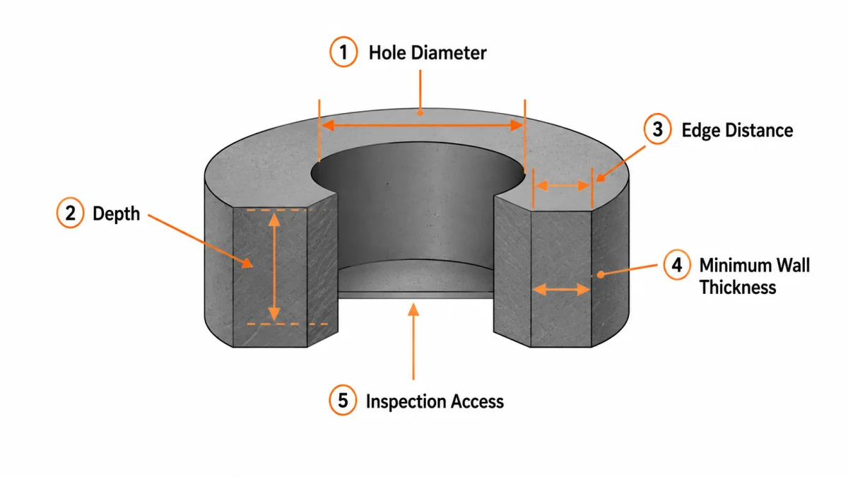
Small holes and thin walls cannot be judged from one dimension. A hole below 2 mm may be short and well supported or deep, blind, near an edge, inside a narrow bridge, or difficult to inspect. Depth above six times diameter raises review attention, but grade, drill geometry, runout, entry support, exit condition, debris evacuation, and positional or surface requirements decide the actual risk.
The DFM review should state whether the hole is through or blind; define the entry and exit edge; identify hole-to-edge and hole-to-hole distances; show any counterbore, chamfer, thread, or intersecting passage; and confirm how diameter, depth, and position will be measured. A blind hole removes the through-hole exit face but introduces bottom geometry, depth, and debris-removal considerations. It is not always a lower-risk substitute for a through hole.
A wall below 2 mm or an unsupported height above four times wall thickness should start a support and handling review. Check whether adjacent pockets remove support, whether the wall can remain thicker until the final operation, whether contact measurement could deflect it, and how the finished part will be cleaned and separated in the package.
- Confirm the named graphite grade, grain structure, strength direction, and relevant material-lot requirements.
- Mark hole entry, hole exit, edge distance, hole spacing, slot width, bridge width, and unsupported wall height.
- Define acceptable chamfer, radius, edge break, and visible chip limits rather than using “sharp” without a measurement rule.
- Confirm tool and probe access for deep, recessed, or intersecting features.
- State whether the part is inspected in a free state or on a defined support fixture.
- Include cleaning, lifting, separation, and packing controls for fragile sections.
The articles on thin walls and small holes and graphite machining challenges provide more process context. The exact drawing and named grade remain decisive.
5. Define the Material by Grade or an Approved Property Envelope
Drawing tolerance cannot be separated from material selection. “Graphite” is not one uniform material. Synthetic graphite grades can differ in forming route, grain structure, porosity, density, strength, hardness, electrical resistivity, thermal properties, purity, and anisotropy. A density value alone does not define strength, machining response, contamination suitability, or achievable precision.
When the buyer already specifies a grade, the RFQ should use the full manufacturer and grade designation, required certification, permitted substitutions, and any lot-control requirement. When no grade is fixed, the buyer should describe the service conditions and approve either a named proposed grade or a defined property envelope before production. The property envelope may include density, flexural or compressive strength, grain or pore structure, ash or elemental limits, thermal or electrical properties, and orientation requirements when relevant.
SGL Carbon’s isostatic graphite information and its material pages for extruded and vibration-molded graphite illustrate that forming routes and grades have different structures and property profiles. POCO/Entegris grade data provide a further example of a named grade with a defined property set. These sources support grade-specific selection; they do not prove that a particular our team project can meet a drawing without a separate review.
Applications such as semiconductor-related equipment, vacuum furnaces, metallurgy, continuous casting, EDM tooling, and industrial fixtures may prioritise different material characteristics. The graphite block page provides product context, while the guide to graphite block selection mistakes explains why a general grade label or density number is not enough.
6. Agree the Measurement and Acceptance Method Before Machining
A tolerance statement is incomplete when the measurement basis is not defined. The drawing or inspection plan should identify the datum scheme, measurement locations, support condition, contact or non-contact method, measuring force when relevant, temperature condition, feature calculation, visual magnification, and record required for release. Porous graphite surfaces, dust, contact force, edge condition, and part support can influence readings.
NIST references support measurement uncertainty, metrological traceability, and fitness for purpose. They do not prescribe a ±0.05 mm graphite tolerance, a 0.2 mm chip limit, a particular gauge, or a universal sampling frequency. NIST notes that traceability alone does not guarantee that a result is suitable for the intended decision; the uncertainty of the actual measurement process must also be evaluated. See the NIST material on metrological traceability, uncertainty and dimensional calibrations, and dimensional-metrology publications.
| Requirement | Suitable method example | Main uncertainty source | Project control |
|---|---|---|---|
| OD/ID fit; example ±0.05 mm with readings at 0°/90°/180°/270° | Micrometer, bore gauge, CMM, or approved functional gauge | Contact force, alignment, temperature, pore contact, roundness | Define datum, force or gauge method, angular locations, free-state condition, and reporting rule. |
| Flatness; example 0.05 mm across a 100–200 mm span | Surface plate and indicator or CMM | Support points, dust, local porosity, part deformation | Clean and support consistently; define calculation and whether the surface is evaluated free or restrained. |
| Hole position; example positional tolerance 0.05 mm from datums A/B/C | CMM or optical coordinate method | Datum establishment, probe access, feature calculation, edge quality | Define datum simulators, measured feature construction, and reporting convention. |
| Thin wall | Low-force contact or optical method | Compression, edge damage, local bow, support condition | Specify force or non-contact method and exact measurement locations. |
| Sharp edge; example maximum edge break 0.2 mm at 5×–20× | Optical magnification plus dimensional check where practical | Lighting, interpretation, orientation, local chip shape | Define maximum edge break or chip rule, magnification, lighting, viewing direction, and disposition. |
The approved drawing and inspection plan should state which dimensions are measured, which methods are permitted, how uncertainty is handled, and whether the order requires a certificate, dimensional report, photographs or raw measurement records.
7. Approve the First Article and Sampling Plan by Risk
First-article approval should close the open questions created by a new drawing revision, new material grade, new setup, or changed inspection method. It should verify that the same product definition, material identity, datum scheme, measurement method, and acceptance rule are being used by the buyer and our team. A first article is not only a sample part; it is a documented comparison between the approved requirement and the actual evidence.
The small-lot example below shows one risk-based way to set inspection frequency. The actual plan should follow the drawing, criticality, lot size, process history, customer standard, measurement time, material-lot changes, tool or setup changes and the consequence of an escape.
| Lot or feature condition | Frequency | Evidence and escalation |
|---|---|---|
| First article on a new revision or grade | 100% of identified critical dimensions, form controls, small holes, and protected edges | Release only after the requirement, method, result, and disposition are approved. |
| Pilot lot of 3–5 pieces | 100% of critical features on all pieces; general dimensions at least on first and last | Use actual spread to set tool-life, support, cleaning, and interval controls. |
| Stable lot of 50 pieces | Critical diameter every 5 pieces; one full dimensional at first, middle, and last | Escalate to additional or 100% inspection when an approved action rule is reached. |
| Tool replacement or setup interruption | Repeat affected critical features on the first part after restart | Link the result to the tool, setup, material lot, and operator or programme revision as applicable. |
| Packing release | 100% piece and package count; visual edge check where edge damage is critical | Do not allow accepted parts to become nonconforming during cleaning, handling, or packing. |
Specification limits and process action limits are different. In the example of a 30.000 ±0.050 mm diameter, readings moving from 29.990 mm to 30.030 mm across five checks remain inside the drawing limits, but the 0.040 mm directional movement may justify tool or setup review. It should not be called an SPC control-limit violation unless a defined statistical method, data basis, and approved action limit exist. The production record should clearly label drawing specification limits, internal warning limits, and stop or escalation rules.
Our manufacturing controls and machining-process review explain how we maintain the approved geometry through tooling, support and first-article inspection.
8. Protect the Accepted Geometry Through Packing Release
Inspection approval does not protect a graphite part after it leaves the measurement area. Thin walls, sharp edges, precision bores, small holes, and finished contact surfaces can be damaged during cleaning, lifting, stacking, separation, carton handling, or international transport. Packing requirements should be reviewed with the drawing instead of being added after production.
For drawing-based projects reviewed and accepted by our team, packing release can identify protected faces, permitted contact points, piece separation, plugs or covers, soft barriers, orientation, movement restraint, package count, label information, photographs, and any prohibition against pressure on fragile features. The design should protect the actual geometry without introducing contamination or trapping loose debris in critical holes.
A ring with a narrow wall may need individual support; a plate with small holes may need clean separation and face protection; a long thin component may need a rigid carrier; and a high-purity or contamination-sensitive part may require a cleaning and barrier system defined for that project. The article on graphite packaging and logistics provides broader shipment context.
Dry graphite machining also requires an occupational dust-control assessment appropriate to the material, process, SDS, and jurisdiction. The NIOSH Pocket Guide entry for synthetic graphite supports United States occupational-hygiene context; it does not define dimensional acceptance or a global packaging rule.
From Drawing Review to Packing Release
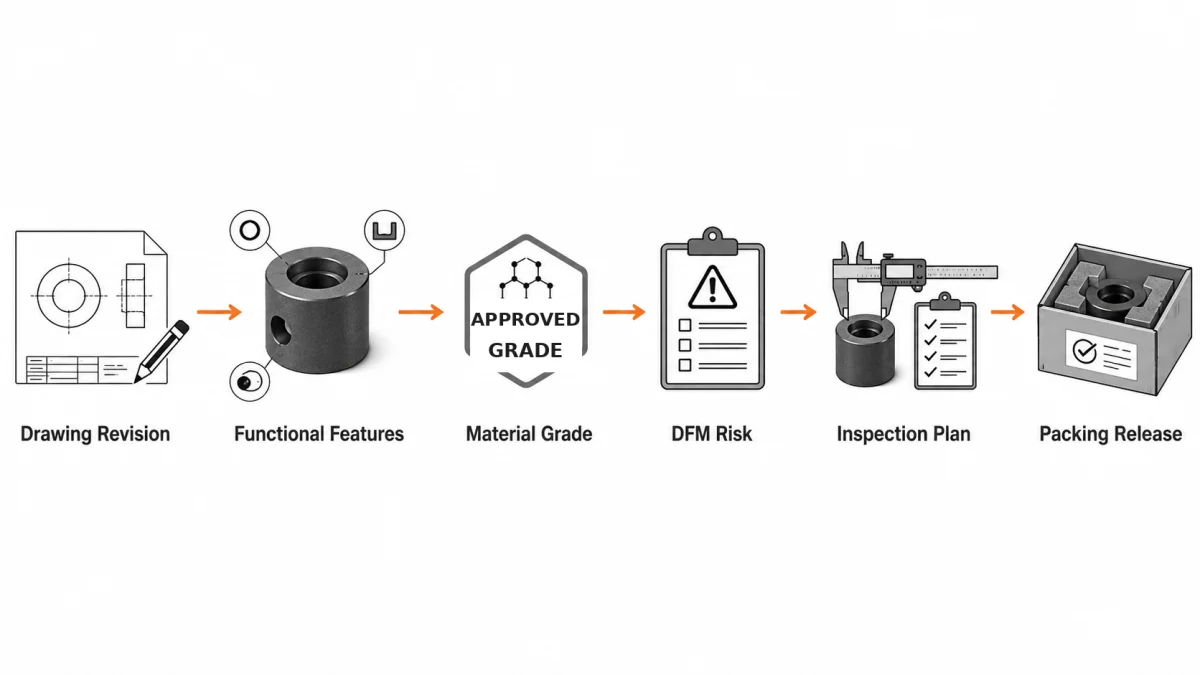
The project can be summarised as six connected controls: Drawing Revision → Functional Features → Material Grade → DFM Risk → Inspection Plan → Packing Release. Each stage closes a different uncertainty. A later stage should not silently compensate for an unresolved earlier one.
Our RFQ Review and Manufacturing Records
Our RFQ review resolves the manufacturing questions that matter to the order. A confirmed repeat order may need only a change check; a new complex part may require documented material, datum and inspection decisions. We connect these decisions to first-article results, traceability and deviation handling rather than adding unnecessary questions.
- Controlling 2D drawing, annotated 3D model, or defined combination, with revision and units.
- Part number, quantity, delivery requirement, and list of obsolete files to ignore.
- Functional dimensions, datums, geometric tolerances, fits, contact surfaces, and edge requirements.
- Small holes, deep holes, blind or through conditions, thin walls, bridges, grooves, sharp corners, and fragile areas.
- Named graphite grade or approved property envelope, certification, substitution rule, and material-lot requirements.
- Application conditions such as temperature, atmosphere, vacuum, contamination, electrical or thermal duty, and contact media when relevant.
- Approved measurement methods, locations, support condition, uncertainty expectation, visual magnification, and reporting format.
- First-article requirement, pilot-lot plan, sampling basis, change-notification rule, and deviation approval route.
- Cleaning, handling, separation, protected surfaces, packing orientation, labels, and shipment evidence.
We identify open drawing points, agree datum and measurement interpretations with the customer, and document feature-specific risks and the material basis before production. The resulting inspection and release records keep quotation, machining and acceptance aligned. Our manufacturing and OEM customization pages describe the related production options.
FAQ: Confirming Drawing Tolerance for Custom Graphite Parts
Must every project use a dimensioned 2D drawing?
No. The RFQ must identify the controlling product definition. It may be an approved 2D drawing, an annotated 3D model, or a defined combination. The revision, units, approval status, and conflict rule must be clear before quotation.
Are ±0.10 mm, ±0.05 mm, and ±0.025 mm standard tolerances?
No. They are drawing-review starting bands used to trigger the appropriate technical discussion. The final commitment is feature-specific and depends on grade, size, geometry, support, tool access, quantity, environment, and measurement method.
Why are holes below 2 mm and depth above 6× diameter reviewed?
They can increase tool, evacuation, exit-edge, inspection, and breakage risk. They do not create an automatic rejection. The through or blind condition, edge distances, grade, support, access, and consequence of failure must also be reviewed.
Why are walls below 2 mm or above a 4:1 unsupported-height ratio reviewed?
These conditions can increase deflection, chipping, handling, and measurement risk. Continuous walls, interrupted walls, local pockets, support strategy, grade strength, and packing may lead to different conclusions.
Does calibration traceability prove a measurement is suitable?
No. Traceability is important, but the method, uncertainty, support, contact force, environment, and decision rule must be suitable for the actual feature and tolerance.
Is the 3–5 piece pilot and 50 piece lot plan mandatory?
No. The example shows the logic of risk-based sampling; the approved plan can use different frequencies according to customer requirements, criticality, lot size, history, process stability and the consequence of an escape.
How does packing relate to tolerance?
A conforming part can become nonconforming if a thin wall, bore, small hole, sharp edge, or contact face is damaged after inspection. Packing release should protect the accepted geometry and cleanliness condition.
References and Scope
- ASME Y14.5 — dimensioning and tolerancing language for drawings and digital models.
- ASME Y14.41 — digital product-definition data practices.
- NIST Metrological Traceability — traceability and fitness-for-purpose boundary.
- NIST: Uncertainty and Dimensional Calibrations — dimensional measurement uncertainty.
Discuss Custom Graphite Part Drawings with us
For drawing-based projects reviewed and accepted by our team, the quotation and controlled order file can identify the governing product definition, revision, functional features, material grade, small-hole and thin-wall risks, measurement method, first-article evidence, sampling basis, and packing-release requirements. The exact scope is agreed for the project and is not inferred from a general article.
QDZRT Graphite reviews custom graphite machining inquiries for rings, molds, plates, bushings, fixtures, electrodes, furnace components, and other drawing-based parts. Start the inquiry through the contact page with the quantity, application conditions, critical characteristics, and required evidence. After we reply, send approved drawings, CAD files, and other controlled project files by email or another agreed secure channel.
Product information is available for Custom Graphite Machined Parts. Application references include EDM tooling, high-temperature processing, and semiconductor graphite parts.