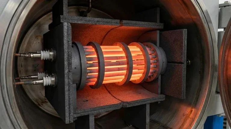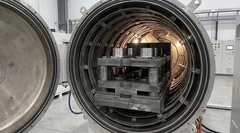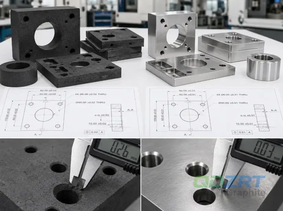
A metal-part drawing cannot be transferred to graphite unchanged.
QDZRT Graphite reviews the intended function, material grade, datum structure, hole geometry, wall support, edge policy, inspection condition, and packing method before quotation.
A drawing can contain correct size dimensions and still leave the supplier unable to verify flatness, parallelism, hole-position risk, free-state shape, or acceptable edge condition.
| Drawing feature | Numerical review trigger | Reason |
|---|---|---|
| Flatness/parallelism | Tolerance below 0.05 mm on a broad or thin section | Project-review trigger: support, datum, free-state condition, and measurement method become critical. |
| Small hole | Diameter below 2 mm; depth above 4× diameter requires enhanced review; above 6× diameter is high risk | Tool access, drill stability, breakout, dust evacuation, remaining wall, and gauge method need review. |
| Hole near edge | Hole-edge clearance below 3× diameter requires review; below 1.5× diameter is high risk | Local breakout, clamping, cleaning, packing, and remaining-ligament strength require project-specific confirmation. |
| Thin wall | Below 2 mm or height above 4× thickness | Machining sequence, support, cleaning, measurement force, and packing can damage or distort the wall. |
| Internal corner | Specified radius below the available finishing-tool radius | Special tooling, relief, a larger radius, or a drawing change may be required. |
Review basis: The numerical values below are DFM triggers used to decide where the drawing needs closer review. Final feasibility is checked against the named grade, blank orientation, part size, local geometry, tool access, support, quantity, cleanliness, packing and agreed inspection method.
The review covers size, form, orientation, location, runout, holes, walls, corners, material grade, measurement and quotation scope before a custom graphite part is released for production.
Functional requirement: Size tolerances alone do not establish whether a graphite part will assemble, seal, rotate, locate or survive handling. Functional faces and features need the datum references, geometric controls, edge definitions and inspection method that describe the actual fit or performance.
1. Size Tolerances Alone Do Not Control Graphite Part Function
A drawing can list acceptable size dimensions and still fail to define whether the part will seat, align, seal, or rotate as intended.
The buyer wrote this on the drawing:
But they didn’t write:
- Flatness across the contact face
- Parallelism between two mounting surfaces
- Perpendicularity of a hole to the seating face
A size tolerance such as ±0.05 mm controls size; it does not define flatness, parallelism, perpendicularity, circularity, or position. Synthetic graphite is a manufactured porous material whose behavior depends on raw materials, forming route, heat treatment, grain and pore structure, and grade design. Broad or thin sections can also respond to support, clamping, dust, and measurement force, so size and geometric requirements need separate evaluation.
When Form Tolerances Actually Matter:
| Application | What to Specify |
|---|---|
| Sealing face / gasket seat | Flatness, surface finish |
| Heat spreader / thermal contact | Flatness, parallelism |
| EDM electrode mounting face | Flatness, perpendicularity |
| Clamping fixture jaw | Parallelism |
Drawing example: 100 × 50 × 10 mm, size tolerance ±0.05 mm, flatness ≤0.03 mm, and parallelism between face A and face B ≤0.03 mm. The point is to show how size and form controls can be stated separately when the function requires both.
A feature-specific geometric control gives manufacturing and inspection a common acceptance basis instead of relying on overall size alone.
Form controls such as flatness, parallelism, perpendicularity, position, circularity, and runout express different aspects of design intent and should not be inferred from size alone.
QDZRT Graphite reviews the functional datum scheme, the free-state or fixtured inspection condition, and the method used to verify each critical feature.
The ASME Y14.5 dimensioning and tolerancing framework provides the general engineering language; the project drawing still has to define the controls actually required.
The tolerance confirmation guide expands this method.
2. Small Holes, Deep Holes, and Holes Near Edges
A 3 mm diameter hole with a depth of 15 mm has a 5:1 depth-to-diameter ratio.
That geometry may be feasible in one fine, uniform grade and high risk in another grade or wall condition.
QDZRT Graphite therefore reviews diameter, depth, entry and exit faces, tool reach, remaining wall, neighboring holes, blank orientation, and inspection access together.
Three Graphite Hole Problems:
1. Hole exit breakout: A through-hole can chip as the tool exits the far side. A controlled exit chamfer, sacrificial support, altered sequence, or a blind-hole design may reduce risk, but a blind hole is not a direct substitute where a through-hole is functionally required.
2. Edge-clearance risk: Unless the drawing defines another convention, QDZRT Graphite measures edge clearance from the finished hole edge to the nearest external edge.
A clearance below 3× the hole diameter enters the review range; below 1.5× diameter is treated as high risk.
For a center-to-edge dimension, add the hole radius to convert from edge clearance.
3. Thin ligament between holes: Neighboring holes or a hole near a pocket can leave a narrow brittle web. The remaining ligament, hole depth, grade, support, cleaning, and packing all affect whether the feature survives.
What to check before ordering:
- Minimum hole diameter relative to grain structure and available tool
- Depth-to-diameter ratio: above 4:1 requires enhanced review; above 6:1 is a high-risk trigger
- Hole-edge clearance and the drawing convention used to dimension it
- Remaining wall to pockets, neighboring holes, and external edges
- Through-hole or blind-hole function, entry face, exit face, and required chamfer
- Tool reach, dust evacuation, inspection access, and acceptable gauge method
If these items are not defined, ask QDZRT Graphite to return a marked drawing-review list before quotation.
The response should identify the affected feature, the trigger used, the open technical point, and any proposed geometry, grade, process, inspection, or packing change.
Hole diameter alone is incomplete. Depth, exit condition, edge distance, neighboring holes, remaining wall, tool reach, and inspection access determine risk. See thin walls and small holes and graphite machining challenges.
3. Sharp Corners vs. Chamfers and Edge Chipping
A nominally sharp external corner may survive in steel yet chip in graphite during machining, cleaning, inspection, packing, or service. Whether it survives depends on corner geometry, material behavior, support, handling, and acceptance criteria.
Edge condition needs an agreed acceptance rule. The drawing and quotation should distinguish functional and cosmetic edges, permitted edge break, inspection magnification and packing protection so a visible chip is judged against the part function rather than by appearance alone.
What to do about it:
- Decide which edges are functional and which are cosmetic
- For cosmetic edges: a 0.3–0.5 mm chamfer or a small radius usually makes the problem go away
- For functional edges (sealing lips, contact steps): specify them explicitly and discuss edge protection packaging
- Add an edge chipping allowance if you hold the part to tight cosmetic standards
Edge-note example: All non-functional edges C0.3–C0.5 or R0.5; designated functional edges subject to a stated maximum edge break such as 0.2 mm. The final values should match the sealing, electrical, thermal, locating or cosmetic function of the part.
A defined edge policy prevents a cosmetic expectation from being mistaken for a functional requirement or a normal handling allowance.
QDZRT Graphite separates functional edges, measurement references, and cosmetic edges. Functional sharpness receives a maximum edge-break definition and optical acceptance; non-functional edges can use an agreed chamfer. The machining mistakes guide explains the failure chain.
4. Minimum Wall Thickness — Where Parts Actually Break
Drawings do not always identify the local minimum wall created by a deep pocket, narrow slot, long rib, hollow cavity, counterbore, or intersecting hole.
A feature can survive machining and still fail during cleaning, inspection, packing, transport, installation, or service.
Common fragile features to watch:
- Deep cavities with thin floor
- Long, narrow ribs or bosses
- Thin-walled rings
- Parts with large hollow sections and thin outer walls
- Narrow bridges between two machined pockets
RFQ review request:
“Please mark any local wall, rib, floor, bridge, or corner transition that QDZRT Graphite considers high risk during machining, inspection, cleaning, packing, or service.”
When QDZRT Graphite flags a feature, the technical options may include increasing the local wall, adding an internal radius, changing the sequence, leaving temporary support stock, splitting the component, selecting a more suitable grade, changing inspection access, or accepting a documented scrap and handling risk.
The quotation should state which option was assumed.
Minimum wall thickness is local, not global. Height, length, support, holes, corner transitions, grade, and handling change the safe section. A wall that survives machining may fail in cleaning or shipping, so the packing design is reviewed with the toolpath. See graphite packaging.
5. Material Grade Sets the Tolerance Ceiling
Do not pair a lower-cost grade with a tight feature requirement by assumption. The selected grade still has to support the required edge stability, wall strength, surface condition, dimensional repeatability, purity, thermal behavior, and batch consistency; machine positioning cannot compensate for a poorly defined or unsuitable material.
Match Your Material to Your Requirements:
| Graphite selection option | Illustrative project starting range | Typical review context | Boundary |
|---|---|---|---|
| Molded or vibration-molded medium-grain grade | ±0.10 mm | General fixtures, blocks, and robust industrial features | Not a grade guarantee; confirm grain, strength, directionality, part size, local geometry, support, and inspection. |
| Extruded grade | ±0.10–0.15 mm | Rods, tubes, bars, heaters, and direction-aware designs | Axial forming can create anisotropy; blank orientation and property direction must be stated. |
| Fine or ultrafine grade | ±0.03–0.05 mm | EDM electrodes, precision molds, small features, and controlled surfaces | Final capability depends on the named grade, feature scale, tooling, setup, quantity, and measurement method. |
| Isostatically molded fine or ultrafine grade | ±0.02 mm or better | High-stability, high-purity, semiconductor, vacuum-furnace, or precision applications | Isostatic forming alone does not guarantee the value; named-grade data, geometry, process study, and first-off inspection are required. |
Boundary: These ranges are QDZRT Graphite project-review starting points, not standard catalogue tolerances.
Final capability is confirmed against the named grade or approved property envelope, blank orientation, part dimensions, wall and hole geometry, tool access, fixture strategy, production quantity, thermal condition, cleanliness, and inspection method.
If the grade is not specified, provide QDZRT Graphite with the application, service atmosphere, temperature, load, electrical or thermal function, purity, surface requirement, assembly fit, quantity, and expected inspection record.
This allows the quotation to identify a named grade or an approved property envelope instead of using density alone.
- What the part does (sealing, heating, conducting, positioning, sliding)
- What temperature range it works in
- Whether surface finish matters functionally or only cosmetically
- Whether the part touches another component (assembly fit)
QDZRT Graphite can then propose a material selection and identify which properties still require customer approval.
Official material references show that isostatic, extruded, and vibration-molded graphites can differ in isotropy, grain structure, and directional behavior, while suppliers offer multiple named grades within the same application family.
See SGL Carbon’s graphite manufacturing overview,
extruded and vibration-molded graphite information, and
POCO/Entegris EDM grade portfolio.
Machine positioning cannot overcome a material that cannot support the feature. QDZRT Graphite links the named grade, batch, forming method, and property data to the drawing. Stock options are described on Graphite Block and the block selection mistakes guide.
6. Six Reasons Tight Tolerances Increase the Quote
Changing a drawing from ±0.10 mm to ±0.02 mm can materially change the quotation, but QDZRT Graphite does not apply a universal percentage increase.
The effect is calculated from the affected feature, grade, part size, blank allowance, machining sequence, tool access, support, inspection, quantity, expected yield, cleaning, and packing.
- Material and blank allowance: a more uniform named grade, larger blank, or added stabilization stock may be required.
- Staged machining: roughing, rest, cleaning, semi-finishing, and final finishing may replace a single-pass sequence.
- Fixture and support development: broad, thin, ring-shaped, or fragile parts may require distributed support and repeated re-indication.
- Dedicated tools and controlled engagement: tool condition, reach, runout, and finishing allowance become more sensitive.
- Inspection and documentation: feature-specific gauges, optical methods, a surface plate, CMM time, repeat readings, and a formal report may be required.
- Yield, cleaning, and packing risk: a part acceptable under a general requirement may be rejected when edge, form, surface, or free-state criteria are tightened.
The quotation should separate these cost drivers rather than presenting a generic tolerance surcharge.
A tight value is retained where it protects function; otherwise QDZRT Graphite can propose a wider production tolerance, a first-article study, or a different inspection plan.
The precision machining guide and
shop-floor parameter guide show how process evidence supports the value.
7. How to Send a Graphite RFQ That Gets a Useful Quote Back
A useful QDZRT Graphite RFQ provides enough controlled information to price the material, process, inspection, cleaning, and packing without relying on assumptions.
On the drawing or in the email — checklist:
- ☐ Latest drawing revision with units
- ☐ Edge treatment: chamfer allowed? radius?
- ☐ Critical dimensions and their tolerances
- ☐ Material grade if known; if not, describe environment
- ☐ Form tolerances for functional faces
- ☐ Surface finish requirement
- ☐ Minimum wall thickness — ask supplier to review
- ☐ Application field
- ☐ Small hole details: diameter, depth, edge distance
- ☐ Sample batch before production?
Recommended RFQ sentence: “Please mark the features that QDZRT Graphite considers difficult or high risk in graphite and identify the drawing, material, process, inspection, or packing information needed before order confirmation.”
This request creates a documented review step and gives the customer a clear list of open technical points before material release.
The RFQ includes one revision, units, material or application, quantity, critical dimensions, edge policy, cleanliness, inspection, and packing. Finished components follow Custom Graphite Machined Parts. Relevant contexts include EDM tooling and high-temperature processing.
8. QDZRT Graphite Drawing Review Before Quotation
For a custom graphite ring, plate, block, fixture, mold, bushing, electrode, heater, or precision component, QDZRT Graphite reviews the drawing against graphite material behavior, machining access, inspection, cleaning, handling, and packing before releasing a quotation.
Contact QDZRT Graphite with your drawing and requirements.
Prepared by the QDZRT Graphite Engineering Team as a project-review guide; final capability and acceptance criteria remain drawing-, grade-, process-, and inspection-specific.
QDZRT Graphite returns open technical points before material release. The review can identify a required radius, split operation, support feature, inspection limitation, or packing restraint. Supplier and customization controls are covered in manufacturer selection and OEM customization.
A Practical Graphite Drawing-Review Sequence
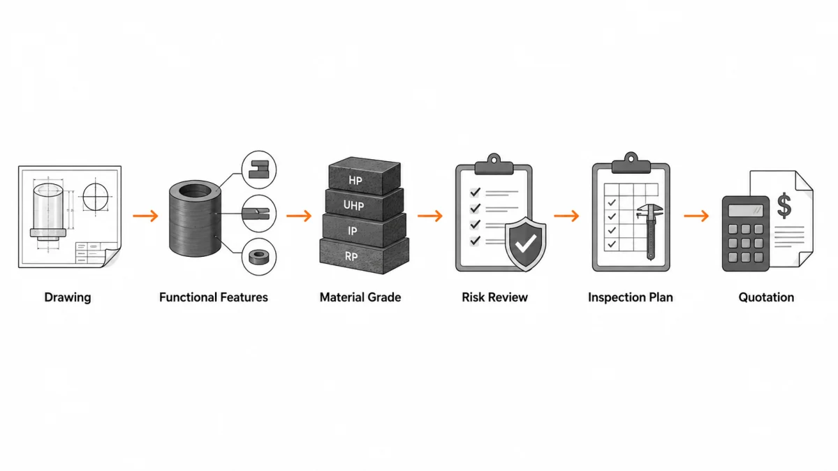
QDZRT Graphite organizes the review in six linked stages: Drawing → Functional Features → Material Grade → Risk Review → Inspection Plan → Quotation.
A feature is not released merely because it can be drawn or nominally machined; its function, material, process risk, measurement, and commercial boundary must close together.
Datum-to-Feature Review Map
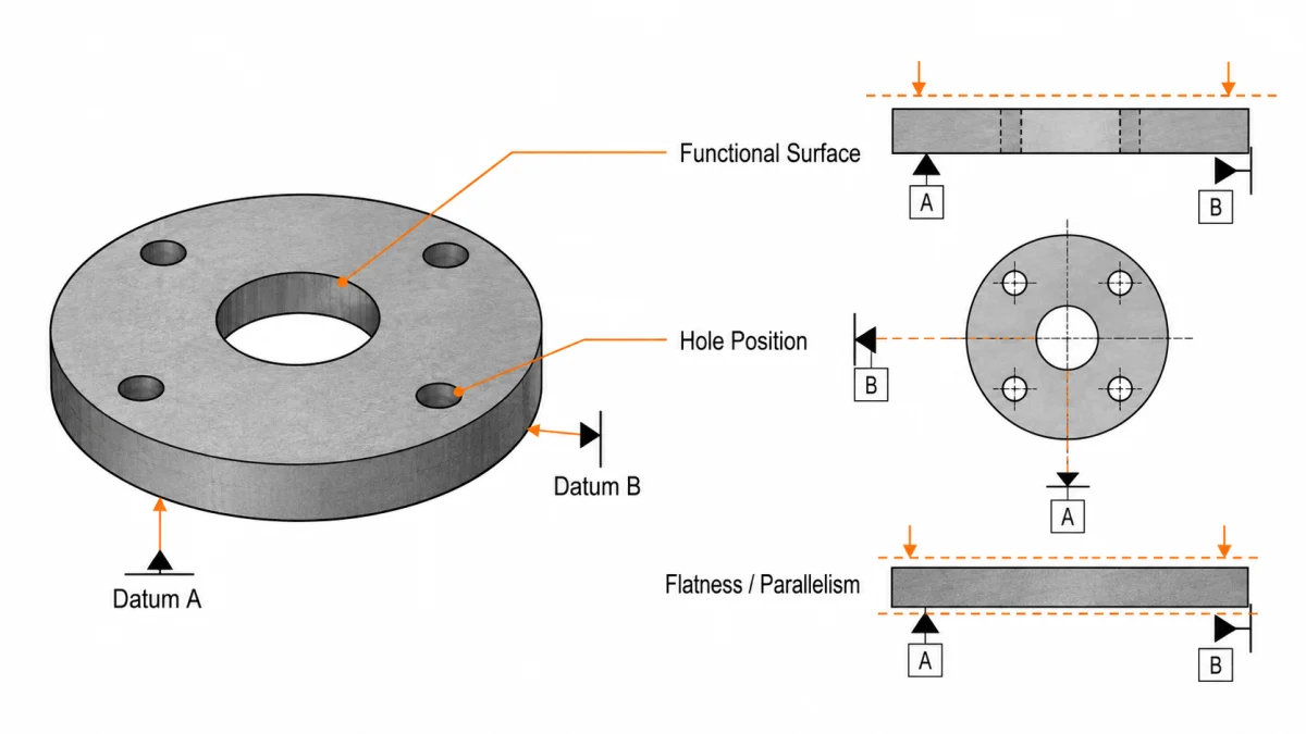
| Feature | Primary datum question | Manufacturing question | Inspection question |
|---|---|---|---|
| OD/ID ring fit; review ±0.05 mm or tighter and wall below 2 mm | Which diameter establishes the axis? | Can the ring remain supported without ovality? | Measured free-state or in a fixture; at what locations? |
| Flat sealing face; review flatness below 0.05 mm across spans above 100 mm | Which opposite face or points define the datum? | How is support maintained during finishing? | Flatness method, contact points, and clean condition? |
| Hole pattern; review position below 0.05 mm or hole-edge clearance below 3× diameter | Which faces and origin locate the pattern? | Can all holes be reached while preserving the required ligament and exit condition? | CMM/optical/gauge method and positional basis? |
| Deep pocket | Which top face and side datums control depth/location? | How are dust and tool reach managed? | Probe access and bottom-surface acceptance? |
| Thin rib | Which stable surfaces locate the rib? | When is support stock removed? | Optical method, edge-break limit, and handling rule? |
For semiconductor contexts, see semiconductor graphite parts. For EDM electrodes, see EDM graphite electrodes. These applications use the same drawing-review discipline but assign different functional priorities.
Worked Drawing Review: Graphite Ring
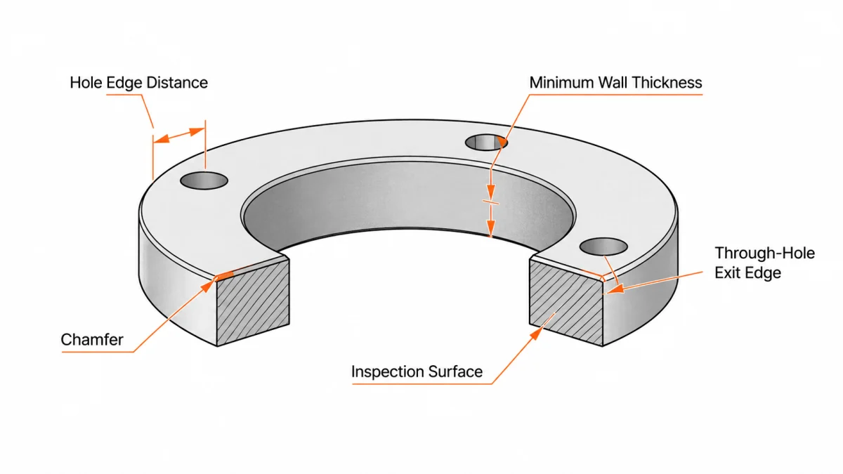
Consider a graphite ring with an outside diameter of 120.00 ±0.05 mm, an inside diameter of 90.00 ±0.05 mm, thickness of 8.00 ±0.05 mm and face flatness of 0.05 mm. The review first determines which diameter establishes the functional axis, whether the ring is measured free-state or on a mandrel, and which face establishes axial location.
Material selection then considers ring wall width, service temperature, atmosphere, contact load, purity, and the risk of edge loss. A grade selected only from density can still have unsuitable strength, pore structure, or directional behavior. The approved grade and batch identity are linked to the ring part number. Blank allowance is chosen to remove surface condition and establish both faces without leaving an unsupported thin section too early.
- Setup 1: establish the primary face and a reference diameter while the ring retains maximum section support.
- Setup 2: finish the opposite face and controlled diameter using distributed support; avoid concentrated force that creates temporary ovality.
- First-off inspection: measure OD and ID at multiple angular locations, thickness at defined points, and flatness on a clean support condition.
- Re-fixture check: repeat one diameter and flatness after unclamping and cleaning to reveal support or dust effects.
- Edge acceptance: define the permitted chamfer, radius, or maximum chip instead of relying on “sharp edge” wording.
- Packing: support the broad faces, isolate each ring, and prevent the OD/ID edges from carrying carton or stack load.
Suppose the first free-state OD readings are 120.03, 120.01, 119.98, and 120.02 mm. All four lie inside the illustrative ±0.05 mm size tolerance, but the 0.05 mm spread also prompts a review of roundness, support, and measurement location. A single average value would hide that information. If the drawing controls circularity or concentricity, those characteristics require their own datum and method; size readings alone do not establish them.
The same logic applies to flatness. A clean free-state surface-plate or CMM result is not interchangeable with a reading taken while the ring is clamped. The inspection report therefore records condition, support, method, instrument or gauge class, nominal, tolerance, individual results, and disposition. Where measurement uncertainty is a large fraction of the tolerance width, the method is improved or the acceptance decision is qualified rather than presenting false precision.
Finally, the drawing review closes the commercial scope. Quantity, first-article approval, sampling, report format, cleaning, marking, and packing are written into the quotation. The precision graphite machining guide provides the control-stack context, while the thin-wall and small-feature article explains how geometry changes risk and price.
This worked review also shows why every numerical tolerance needs a defined datum, part state, measurement location, and acceptance method.
Frequently Asked Questions
Why can a metal drawing be risky when converted to graphite?
Metal drawings often assume ductile edges, threaded strength, clamping tolerance, and machining access that do not transfer directly. Graphite is brittle and grade-dependent. QDZRT Graphite preserves the intended function while reviewing wall thickness, hole position, radii, datums, surface requirements, inspection force, and packing.
Which drawing controls matter most for graphite parts?
The answer depends on function, but flatness, parallelism, runout, hole position, wall thickness, pocket depth, and edge condition are common. Each control requires a stable datum and an inspection method. A broad general tolerance cannot replace feature-specific controls where assembly, sealing, electrical, or thermal performance is involved.
How close can a hole be to a graphite edge?
There is no universal distance.
QDZRT Graphite uses hole-edge clearance below 3× diameter as a review trigger and below 1.5× diameter as a high-risk trigger, measured from the finished hole edge to the nearest external edge unless the drawing states another convention.
Hole diameter, depth, exit direction, remaining ligament, neighboring features, grade, support, inspection, cleaning, and packing still determine the final decision.
Should every graphite edge have a chamfer?
No. Functional edges may need to remain sharp or follow a defined maximum edge break. Cosmetic or handling edges often benefit from a controlled chamfer. The drawing should identify critical edges; QDZRT Graphite then applies the correct toolpath, inspection magnification, cleaning, and packing protection.
How are thin graphite walls measured?
Low-force contact, optical, or coordinate methods may be used depending on geometry and tolerance. The wall must be measured from stable datums without compression or chipping. QDZRT Graphite defines locations, force or method, and free-state condition before production. Packing then supports the wall without changing its accepted shape.
Why do tight tolerances change the material choice?
A coarse, variable, or directional structure may not support the same edge, surface, and dimensional stability as a fine uniform named grade, but forming route or grain label alone does not determine capability.
QDZRT Graphite reviews the complete grade data, blank orientation, feature scale, setup, quantity, and measurement method and confirms whether a named grade or approved equivalent can reproduce the requirement.
What files produce the fastest drawing review?
Provide the latest 2D drawing with revision and units, a 3D model for geometry, material or application, quantity, critical-feature mark-up, assembly context, inspection method if prescribed, and packing/cleanliness needs. A used sample should be identified as worn or modified so its measured dimensions are not assumed to be the original design.
References & Sources
- ASME Y14.5 — Dimensioning and Tolerancing: supports the engineering language for size, form, orientation, location, and runout controls.
- NIST — Uncertainty and Dimensional Calibrations: supports feature-specific measurement uncertainty and method control, not graphite-specific wall, hole, or tolerance limits.
- NIST — Metrological Traceability: supports documented measurement relationships and traceability.
- NIOSH Pocket Guide — Graphite (Synthetic) and OSHA Chemical Data — Graphite (Synthetic): U.S. occupational references for synthetic-graphite dust; facilities must confirm material identity, SDS, local law, and exposure controls.
Send a Graphite Drawing for DFM Review
Start the inquiry through the QDZRT Graphite contact page with the revision, units, named grade or application, quantity, critical features, datum expectations, inspection condition, cleanliness, and packing requirements. After we reply, send the controlled 2D drawing, 3D CAD file, and other project documents by email or another agreed secure channel.
QDZRT Graphite will return a feature-specific list of assumptions, review triggers, open technical points, and quotation boundaries before material release.