Semiconductor-related graphite parts are usually small details inside a much larger process. A graphite support, plate, ring, fixture, carrier, or thermal component may not look complex at first, but its material grade, purity level, surface condition, and dimensional stability can affect how reliably the equipment runs.
| Semiconductor graphite control | Published reference | Order implication |
|---|---|---|
| Purity | Named purified graphite options may reach the ppm impurity range, including specifications near 5 ppm or 99.9995% when the selected grade, test method, and order require that basis. | Specify purity basis, test method, and whether the value applies to raw material or finished parts. |
| Commercial grain segmentation | Published fine-grain graphite portfolios can span approximately 1–10 µm particle-size ranges, including grades around 1, 5, and 10 µm; category names and particle metrics vary by manufacturer. | Match structure to part size, detail, coating, and process duty. |
| Post-processing | Densification can substantially reduce open porosity. | Purification, densification, coating, and impregnation are different operations and must be ordered separately. |
| Measurement | NIST treats every measurement as an estimate with uncertainty. | Critical dimensions need defined datums, methods, environment, and reporting—not only tolerance values. |
| Dust | OSHA synthetic graphite references 15 mg/m³ total and 5 mg/m³ respirable. | Use engineered extraction while separately controlling product cleanliness and cross-contamination. |
Scope boundary: “Semiconductor grade” is not one universal grade. Crystal growth, epitaxy/MOCVD, ion implantation, furnace hardware, dry etch, and handling fixtures can require different purity, coating, density, CTE, geometry, and cleanliness controls.
For these parts, the question is not simply whether graphite can be machined. The better question is: has the graphite grade, geometry, tolerance, and handling requirement been matched to the actual process environment?
Process requirement
Semiconductor-related graphite parts should be reviewed as process-sensitive components. A drawing is necessary, but the production scope must also define purity expectations, temperature, atmosphere, contact surfaces, cleaning needs, and packaging requirements before material release.
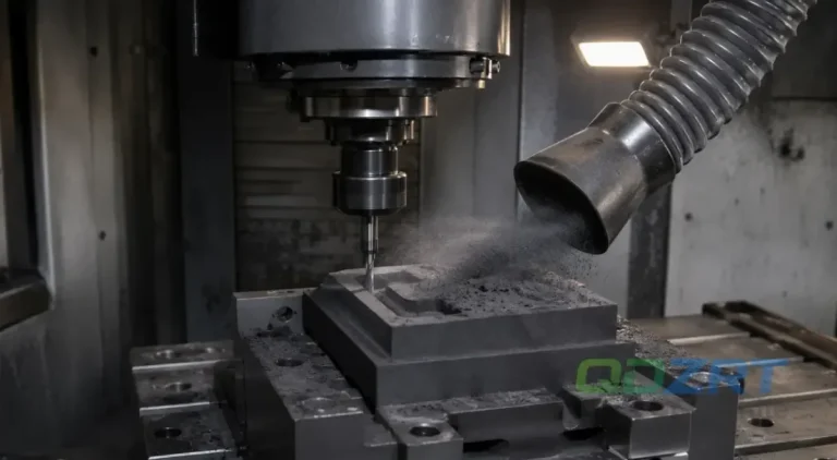
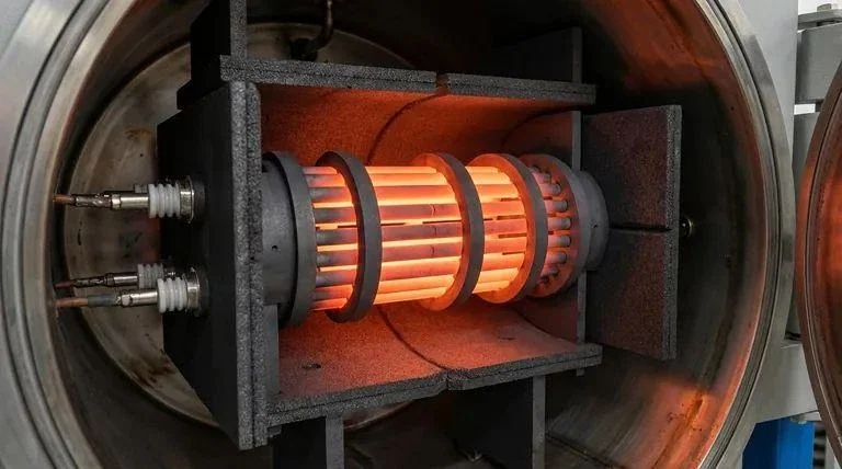
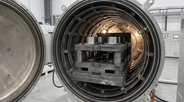
Graphite is used in many high-temperature, thermal, electrical, and contamination-sensitive industrial environments. In semiconductor-related equipment, graphite parts may be selected because they offer thermal stability, machinability, and suitable performance in controlled process conditions.
The Semiconductor Industry Association reported global semiconductor sales of $791.7 billion in 2025. That market scale explains why repeatability and supply continuity matter, but it does not create one universal graphite specification. High-purity graphite, coated graphite, and precision-machined components are selected according to the actual equipment process.
Application note: The same machined shape can require different graphite material depending on where it works. A fixture used in high-temperature processing, a plate used for support, and a small precision component near a cleaner process area should not be quoted only by outside dimensions.
RFQ risk
If the supplier receives only a drawing with no application notes, the part may be machined to size but still be unsuitable for the operating temperature, atmosphere, purity expectation, or handling requirement.
RFQ example
“This part is used in semiconductor-related equipment. Please review the drawing together with the working temperature, atmosphere, purity expectation, contact surfaces, and packaging requirement before quoting.”
Process context determines the contamination mechanism and the functional property. A graphite heater in a crystal-growth hot zone is evaluated differently from a SiC-coated susceptor, a wafer-processing fixture, or an auxiliary furnace component. Toyo Tanso describes ppm-order purification, high-purity graphite, and SiC-coated susceptors for crystal growth, epitaxy, and MOCVD in its semiconductor manufacturing application guide. SGL Carbon likewise identifies high-purity SiC-coated graphite susceptors for silicon and SiC epitaxy. Temperature, atmosphere, thermal cycling, gas exposure, contact with silicon or process chemicals, electrical function, and replacement interval all influence the grade and post-processing route.
The thermal management and high-temperature processing solution covers high-temperature graphite contexts. For drawing-based components, the Custom Graphite Machined Parts page explains our production route. The article on custom graphite parts in semiconductor, furnace, and EDM applications compares the different service drivers.
2. Match the Graphite Grade Before Confirming the Shape
Semiconductor-related graphite parts may use isostatic, molded, extruded, fine-grain, purified, coated, or other application-oriented graphite material options, but the selected material option must be tied to a named supplier grade and verified documentation. Buyers should review structure, dimensional consistency, impurity basis, and finished-surface requirements against the actual process.
Material selection should come before final machining approval.
If the grade is not suitable, even accurate CNC machining cannot fully solve later problems such as edge weakness, poor dimensional stability, contamination concern, or unnecessary cost.
| Material | Why Buyers Consider It | What to Confirm |
|---|---|---|
| Isostatic Graphite | Uniform structure and good dimensional consistency for precision parts | Geometry, tolerance, surface requirement, operating condition |
| Fine Grain Graphite | Useful when small features, smoother surfaces, or detailed machining are required | Min wall thickness, small holes, edge condition, finished surface |
| High Purity Graphite | Selected when lower impurity level or cleaner process compatibility is important | Purity expectation, cleaning requirement, packaging, process sensitivity |
| Graphite Block | Stock material for plates, supports, fixtures, and custom machined shapes | Block grade, machining allowance, final dimensions, inspection scope |
Material choice should be confirmed by grade, geometry, process temperature, atmosphere, purity expectation, and final inspection requirements.
Grade matching begins with forming method, particle metric, density, strength, porosity, thermal conductivity, coefficient of thermal expansion, and purity. A fine uniform structure can support precision machining and coating, but the largest part size, thermal gradients, and mechanical loading also matter. Entegris describes POCO materials spanning 1–10 µm particle sizes with grade-specific post-processing and coating options in its Industrial Material Solutions guide. The purchasing and engineering teams should review the selected supplier data and should not accept substitution based only on a broad “high-density graphite” description.
Published graphite portfolios include grades across approximately 1–10 µm particle-size ranges, with application-specific variants and manufacturer-defined metrics. The selected grade, rather than a generic size label, controls the approved property basis. Stock material is introduced on the Graphite Block page. The graphite block industrial uses guide explains why forming method and service condition should be tied to the drawing.
| Application context | Material emphasis | Post-processing question | Machining/inspection emphasis |
|---|---|---|---|
| Crystal-growth hot zone | High purity, thermal stability, suitable CTE and strength at size | Purification, densification, coating, or insulation interface? | Concentricity, joint fit, wall stability, and clean handling. |
| SiC-coated susceptor | CTE compatibility, uniform structure, coating adhesion foundation | Coating specification, thickness, coverage, repair policy? | Surface preparation, runout, pocket geometry, and coating allowance. |
| Epitaxy/MOCVD hardware | Purity, particle control, thermal uniformity, process-gas compatibility | SiC or pyrocarbon coating, purification level? | Repeat geometry, surface condition, clean packaging, and traceability. |
| Furnace/implant auxiliary parts | Thermal cycling, strength, oxidation environment, electrical function | Oxidation inhibitor or application-specific treatment? | Hole position, flatness, mounting interfaces, and protected edges. |
| Handling/positioning fixture | Particle generation, contact geometry, dimensional repeatability | Cleaning and surface-sealing requirement? | Contact surfaces, edge condition, wear areas, and inspection frequency. |
3. Purity and Cleanliness Should Be Stated Clearly
Semiconductor-related alone does not mean every part needs the same purity level. Some graphite parts are used in cleaner or more contamination-sensitive positions. Others are used as high-temperature supports, fixtures, or thermal structures where the practical requirement may be different.
The buyer should describe the cleanliness requirement instead of only writing “high purity graphite.”
If the expected purity, cleaning, handling, or packaging condition is not stated, the supplier may not know how strict the finished part needs to be.
A vague purity request can select the wrong material, add unnecessary cost, or leave the finished part mismatched to the process sensitivity.
RFQ information:
- Whether the part is used in a contamination-sensitive position
- Required graphite grade or expected purity requirement
- Whether cleaning before packing is required
- Whether functional faces must be protected during shipping
- Whether the part contacts wafers, tooling, fixtures, furnace hardware, or another component
Purity can be expressed as percent carbon, total ash, or total metallic impurities, and these measures are not equivalent. A statement such as 99.9995% corresponds to 5 ppm by mass only when the measurement basis is clearly defined. The order record should state whether the requirement applies to the incoming block, a test coupon, or the finished machined part after purification and handling.
The High Purity Graphite Powder page covers powder materials, but a powder purity certificate should not be used as evidence for a machined isostatic-graphite component. The graphite purification methods guide explains the difference between chemical and high-temperature purification routes. Cleanliness after machining remains a separate control from bulk purity.
| Purity statement | Equivalent expression | What must be defined |
|---|---|---|
| 99.9% carbon | 1,000 ppm non-carbon by simple mass balance | Test method, volatile matter/ash basis, and whether value is typical or guaranteed. |
| 99.99% carbon | 100 ppm non-carbon by simple mass balance | Same basis plus sampling location and batch rule. |
| 99.999% carbon | 10 ppm non-carbon by simple mass balance | Analytical detection capability and handling contamination become important. |
| 99.9995% carbon | 5 ppm non-carbon by simple mass balance | Confirm ash/impurity method and whether finished parts are purified after machining. |
| <5 ppm impurities | No direct carbon-percent claim unless the method and complete mass basis are stated | Element list, test method, reporting limit, sample condition, and certificate format. |
4. Control Tolerances by Function, Not by Habit
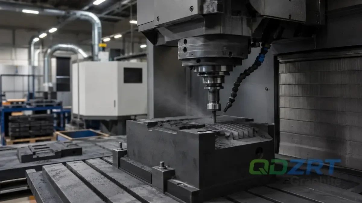
Semiconductor-related graphite parts often include flat faces, locating holes, grooves, steps, thin sections, or precision contact surfaces. Some features may need tighter control, while others only need a practical general machining tolerance.
A useful drawing marks which features are functional.
That allows the supplier to focus machining and inspection effort on the surfaces and dimensions that actually affect assembly, positioning, heating, contact, or process stability.
Drawing note
“Marked faces A and B are functional contact surfaces. Hole positions are critical for assembly. Other non-contact edges may follow general graphite machining tolerance after supplier review.”
Applying very tight tolerance to every surface can increase machining time and inspection cost without improving the part in use.
Functional tolerance is application-specific. Susceptor pockets may require controlled runout and depth uniformity; a heater may require stable resistance-related geometry; a mounting fixture may prioritize hole position and flatness. The drawing owner and supplier should mark the dimensions that influence thermal distribution, contact, alignment, or assembly, then agree the datum and inspection method. General surfaces are not all assigned the same tight value.
The drawing tolerance confirmation guide explains datum and measurement choices. The precision graphite machining guide connects critical features with tool wear and inspection. Measurement reports for semiconductor-related parts should identify the drawing revision, grade/batch, instrument or method, units, and acceptance result.
5. Review Thin Walls, Small Holes, Grooves, and Sharp Edges Early
Graphite can be machined into detailed shapes, but part geometry still matters. SEMI describes silicon wafers as being produced in diameters up to 300 mm, with strong 300 mm demand in advanced applications. Graphite component size is also driven by reactor, furnace, susceptor, and process-chamber geometry; the drawing should not assume an imminent universal transition to a larger wafer format.
Thin walls, small holes, narrow grooves, deep pockets, and sharp edges may affect machining yield, edge strength, cleaning, and packaging.
Geometry risk should be reviewed before production, not after a fragile feature chips.
🔴 Three Geometry Risks to Check:
1
Thin walls — confirm whether the section can survive machining, cleaning, and packing
2
Small holes & grooves — check tool access, dust removal, and inspection method
3
Sharp edges — decide whether the edge is functional or can accept a small chamfer
Geometry note: If a sharp graphite edge is not part of the sealing, locating, or contact function, a small chamfer is often more reliable than a perfect sharp corner.
Evaluate fragile geometry before purification or coating because breakage becomes more expensive after those steps. A 1 mm hole near an edge, tall thin rib, or deep narrow groove can also trap dust or cleaning residue, so geometry, tool access, support, exit direction, cleaning path, coating allowance, and final packing should be planned together.
For geometry-specific review, use the thin-wall and small-hole guide and graphite drawing review. Where SiC or pyrocarbon coating is required, the coating supplier’s minimum radius, masking, thickness, and CTE requirements must be included before the graphite is finish-machined.
6. Inspection and Packaging Are Part of the Requirement
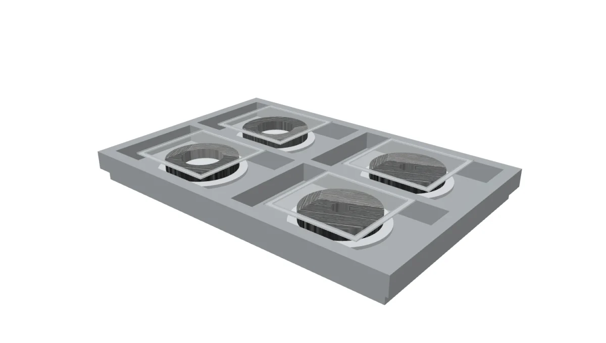
A graphite part for semiconductor-related equipment may pass machining inspection but still be rejected later if dust remains in holes, functional faces are rubbed, or thin edges are damaged during handling. This makes inspection and packaging part of the technical requirement, not only the final shipping step.
The supplier should know which surfaces must stay clean, protected, and dimensionally stable.
Pre-production checklist
- Functional faces and critical dimensions are marked on the drawing
- Material grade or purity requirement is confirmed
- Surface, cleaning, and dust-removal expectations are stated
- Fragile edges, thin sections, and small holes are reviewed
- Packaging protection is matched to the part structure
Inspection and packaging protect the same accepted state. A part measured clean and undamaged can become unacceptable if loose dust, unprotected contact surfaces, or edge-to-edge movement is allowed after release. The order file should define cleaning, visual acceptance, dimensional reporting, part separation, rigid support, labels, and bag or container cleanliness.
The graphite packaging and logistics guide covers fragile parts, while graphite export documentation explains how part identity, quantity, weights, invoice, packing list, and certificates must reconcile. Semiconductor-related packaging may require additional clean-bag, double-bag, or customer-specified controls; these are agreed rather than assumed.
7. What to Send QDZRT Graphite for Review
For semiconductor-related graphite parts, the most useful RFQ includes the drawing and the process context. If the exact graphite grade is not confirmed, the RFQ should request a documented supplier review of the graphite material selection, machining scope, and inspection focus before any equivalence is accepted.
Concise RFQ sentence:
“Please review this graphite part for semiconductor-related use and tell us which material, tolerance, surface, or packaging details should be confirmed before production.”
Recommended RFQ information:
- Drawing, sample, sketch, or target dimensions
- Graphite grade, purity requirement, or application conditions
- Working temperature, atmosphere, and contact environment
- Critical tolerance, flatness, surface, and edge requirements
- Quantity: prototype, trial lot, or batch supply expectation
- Cleaning, inspection, and packaging requirements
A complete review package includes the current 2D drawing, 3D model, part number, revision, exact application stage, atmosphere, temperature range, process gases or contact media where disclosure is possible, grade requirement, purity basis, coating, quantity, critical features, cleaning, inspection, and packaging. When information is confidential, a functional description can still identify the property and contamination risks without disclosing proprietary equipment design.
The inquiry can reference OEM customization options and the custom graphite manufacturer guide. These pages show how grade, drawing, post-processing, inspection, and packing are converted into a controlled order scope.
Semiconductor Graphite Contamination-Control Map
Contamination can enter before, during, or after machining: bulk impurities come with the material; tools and fixtures can transfer residue; dust can redeposit; cleaning can add ions or particles; coating or heat treatment can change the surface; and packing can recontaminate a released component. Map each stage to a check instead of relying on one final purity certificate.
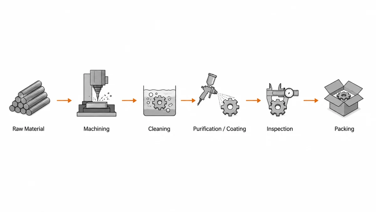
| Stage | Contamination mechanism | Control evidence | Release question |
|---|---|---|---|
| Gate 1 — Raw material; customer-specified purity basis and test method | Bulk metallic/non-carbon impurities or wrong grade | Grade certificate, batch ID, incoming label, and approved source | Is the correct grade and purity basis present? |
| Gate 2 — Machining; record the approved setup and the agreed first-off critical features | Tool/fixture residue, cross-process dust, coolant/oil contamination | Dedicated or controlled setup, dry route where appropriate, tool and fixture condition, and first-off record | Was the part produced under the approved machining and cleanliness route? |
| Gate 3 — Cleaning; verify the defined method and the agreed visual-inspection condition | Incomplete dust removal or introduction of cleaning residue | Defined method, compatible materials, inspection condition | Is the surface state suitable for the next step? |
| Gate 4 — Purification/coating; record lot, specified ppm basis, and coating thickness/coverage where required | Process variation, masking error, incomplete coverage, or post-process damage | Lot certificate, coating record, thickness/coverage report where required | Does post-processing match the drawing and application? |
| Gate 5 — Inspection; define measurement uncertainty and capability appropriate to the tolerance and decision risk | Dirty datums, uncontrolled contact, or handling particles | Clean measurement station, method, gloves/handling rule, report | Was acceptance established without changing the part? |
| Gate 6 — Packing; reconcile part, inner-pack, outer-pack, and shipment counts | Bag/container particles, edge contact, label mix-up | Approved packing specification, clean materials, separation, traceability | Will the accepted state survive storage and shipment? |
Inspection boundary: First-off verification, visual review, measurement capability, and packing-count reconciliation must be defined by the customer-approved inspection plan. No fixed percentage, magnification, or capability ratio is presented here as a universal semiconductor acceptance rule.
Some specialized graphite manufacturers publish ppm-order purification, porosity-reduction treatments, and SiC-coated component routes. These are manufacturer-specific capabilities that require named-grade data, process scope, and certificate review; they must not be assumed to be available from every supplier. This is why bulk material, surface treatment, and finished-part cleanliness must be treated as separate technical controls.
Change Control for Repeat Semiconductor Parts
- Material change: new grade, source, block size, or forming route requires equivalence review and often first-article confirmation.
- Process change: machine, tool, fixture, cleaning, purification, or coating change is assessed against contamination and dimensional risk.
- Drawing change: revision, tolerance, edge, pocket, or hole change is reviewed before existing programs are reused.
- Inspection change: new instrument or method must remain comparable to the approved acceptance basis.
- Packing change: bag, foam, support, carton, or shipment mode change is reviewed for particles and fragile-feature protection.
The approved supplier record should link these controls to the order and batch so repeat production continues from a documented baseline rather than from an old sample alone.
Practical Conclusion
Graphite machined parts for semiconductor-related equipment should be specified with more than just a drawing. In a large and rapidly growing semiconductor supply chain, downtime from a mis-specified graphite fixture, uncontrolled surface condition, or contaminated component can be costly.
The buyer’s job is not to know which graphite grade is best. The buyer’s job is to provide enough context — temperature, atmosphere, function, purity expectation — so the machinist can make that call. A clear RFQ with application notes, marked functional surfaces, and known fragile geometries gives the supplier everything needed to match material, machining, inspection, and packaging to the real service condition.
Final control principle
A stable graphite part starts with a clear technical request. When the supplier understands how the part will be used, it becomes much easier to avoid the common pitfalls of material mismatch, edge damage, tolerance over-specification, and handling failure.
For drawing-based finished components, review our
Custom Graphite Machined Parts page.
For semiconductor stock, furnace hardware blanks, and drawing-based machining material, begin with our Graphite Block specification route.
Frequently Asked Questions
What does semiconductor-grade graphite mean?
It is an application category, not one universal specification. Crystal growth, epitaxy, MOCVD, dry etch, furnace hardware, and handling fixtures can require different grade structure, purity, CTE, strength, coating, and cleanliness. A semiconductor-related order should use a named grade or customer-approved property envelope tied to the specific process and drawing.
Is 99.9995% purity the same as less than 5 ppm impurities?
They are mathematically related by simple mass balance, but the technical claim is valid only when the test basis is defined. Ash, total impurities, selected elements, and carbon content can use different methods. The order should identify the method, sample condition, detection limits, and whether the result applies to raw material or finished parts.
Why are graphite parts purified after machining?
Machining can expose new pore surfaces and introduce handling contamination. Post-machining purification can treat the finished geometry when the grade, size, and subsequent coating permit it, but purification does not replace clean machining, cleaning, inspection, or packing because each stage addresses a different contamination path.
When is SiC coating required?
SiC coating may be used to seal the surface, reduce particle generation, improve chemical/oxidation resistance, or provide process compatibility in applications such as epitaxy and MOCVD. The coating requirement comes from the equipment process. CTE compatibility, surface preparation, radius, masking, thickness, and inspection must be agreed before machining is finalized.
How are critical tolerances chosen for semiconductor graphite parts?
The dimensions that affect thermal uniformity, wafer or component position, electrical function, sealing, rotation, or assembly receive feature-specific control. The drawing owner and supplier should define datums and measurement methods, then verify whether the selected grade and geometry can support the required value. General non-functional dimensions can use a more practical tolerance.
How is cleanliness verified?
Verification may include visual inspection under defined lighting/magnification, particle-control handling, wiping or air-cleaning procedures, customer-specified testing, and controlled packaging. A bulk purity certificate alone does not prove the finished surface is clean. The inspection method and acceptance limit must be defined for the application.
What information is needed for a repeat order?
Retain the approved drawing revision, exact grade and batch rules, purification/coating specification, process route, critical measurements, cleanliness acceptance, and packing. Any proposed substitution or process change should be reviewed against that baseline before production. This is particularly important when a visually similar grade has different purity, CTE, or pore structure.
References & Sources
- Semiconductor Industry Association 2025 Sales Release — Supports the $791.7 billion global semiconductor sales figure for 2025.
- SEMI Q1 2026 Silicon Wafer Shipment Release — Supports the statement that semiconductor silicon wafers are produced in diameters up to 300 mm.
- NIST Dimensional Metrology Publications — Supports only the general measurement uncertainty and method-control discussion.
Submit a Semiconductor Graphite Part for Review
Start the inquiry through the QDZRT Graphite contact page with the application stage, temperature and atmosphere, exact grade or required property range, purity basis, coating, quantity, critical geometry, inspection, cleanliness, and packing. After we reply, send the current controlled drawing and other project files by email or another agreed secure channel. The inquiry should separate material purity, machining control, surface treatment, finished-part cleanliness, and change-control requirements so each item can be confirmed against the actual supplier scope.