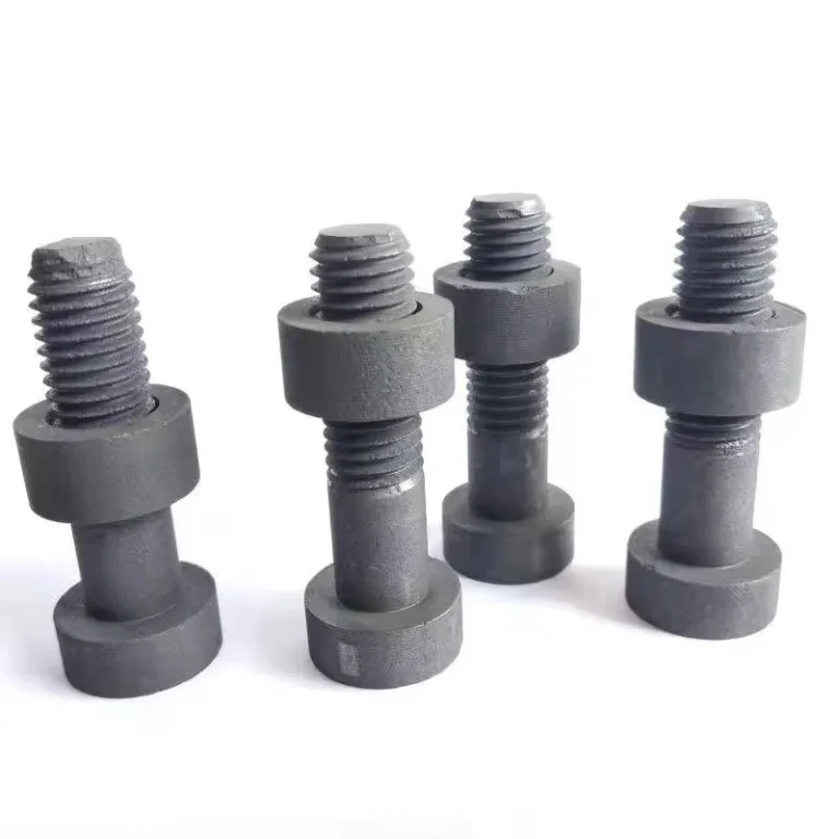
EDM graphite electrodes are used in electrical discharge machining when the electrode must hold detail, conduct electricity, and work through repeated sparking cycles. The electrode is not just a block of graphite. Its grade, grain structure, machining quality, and finished geometry all affect the EDM result.
| EDM decision point | Published or calculated reference | Manufacturing implication |
|---|---|---|
| Broad market descriptions | EDM graphite is often described in broad market categories such as ultrafine, superfine, fine-grain, roughing, or finishing grades. Particle-size definitions and labels vary by manufacturer. | Use the selected grade name and its supplier datasheet rather than treating a market label as a universal specification. |
| Supplier-specific material range to verify | Do not assume one generic EDM graphite range. Confirm the named supplier grade, particle metric, density, resistivity, ash or impurity basis, stock size, and test method from the actual datasheet and batch documentation. | Final values are confirmed against the selected grade datasheet, inspection method, and batch documentation. |
| Thermal and handling difference from copper | Graphite normally has much lower density than copper and behaves differently under thermal and mechanical loading. | Electrode mass, fixture load, chip control, and machining practice should be planned for graphite rather than copied from a copper route. |
| Electrode undersize | Spark gap and electrode undersize must come from the approved EDM technology for the workpiece, duty, flushing, orbit, and required finish; no transferable numeric setting is published here. | Final gap and compensation come from the EDM machine technology, workpiece material, duty, flushing, orbit, and required finish. |
| Polarity and wear | Positive electrode polarity is a common starting convention for many graphite sinker-EDM applications, while negative polarity may be selected for particular machine technologies or duties. | Record polarity, peak current, pulse timing, gap, flushing, and wear results in the EDM process record. |
A successful EDM electrode is a matched system: graphite grade, electrode geometry, machining route, holder datum, burn technology, flushing, and inspection. “Graphite electrode” is a product category, not a complete technical specification.
For many tooling projects, graphite is chosen because it can be machined into detailed shapes and used in demanding electrode applications. The choice is not only graphite versus copper. It is also stock graphite block versus finished custom electrode, rough electrode versus fine-detail electrode, and general tooling versus precision EDM work.
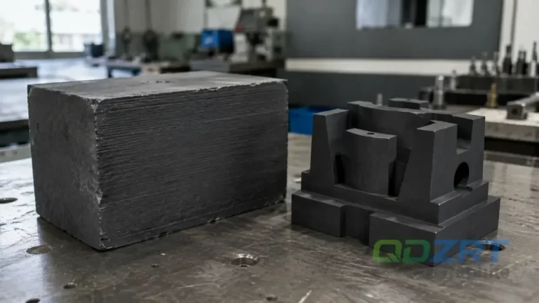
EDM electrode performance starts before the EDM machine runs. Material grade, electrode geometry, surface finish, and machining accuracy all matter.
Why Graphite Is Used in EDM
Graphite has a useful combination of electrical conductivity, thermal stability, machinability, and dimensional behavior. These properties make it practical for EDM electrodes, mold inserts, precision tooling parts, and other components where detail and repeatability matter.
The value of graphite becomes clearer when the electrode has ribs, slots, thin sections, deep detail, or a shape that would be difficult to produce efficiently from another material. Graphite can be milled into complex forms, then used as the working electrode in the EDM process.
Choose the graphite grade from electrode detail, expected wear behavior, surface finish target, and production quantity.
Graphite is used because it can combine electrical conductivity, high-temperature stability, low density, and machinability in a form suitable for complex electrodes. Its practical value becomes clear when several identical electrodes are required, when deep ribs would make a heavy copper electrode difficult to handle, or when roughing and finishing electrodes must be produced from controlled grades. The performance advantage is not automatic: a porous or coarse grade can slow finishing and reproduce unwanted texture in the cavity.
The EDM and precision tooling solution describes our application route from block selection to finished electrode. A broader comparison appears in the graphite block guide for EDM electrodes. These pages separate the material needed for rough stock removal from the material used to preserve small ribs, corners, and final cavity finish.
| EDM objective | Material/geometry emphasis | Typical manufacturing risk | Control evidence |
|---|---|---|---|
| High-removal roughing with a customer-approved finishing-stock allowance | Economical grade with sufficient strength, stable structure, and suitable resistivity | Excessive electrode wear, unstable arcing, or slow removal if grade and power are mismatched | Named grade, roughing technology record, wear result, and cavity stock left for finishing. |
| General-purpose cavity using a named grade and customer-approved finishing-stock allowance | Balanced machinability, strength, wear, and finish capability | Using one electrode for too many stages can lose details or increase polishing | Electrode set plan, rough/finish allowance, and inspection of each datum. |
| Fine ribs and text | Ultrafine or superfine structure, high strength, clean edge machining | Rib breakage during milling, handling, or burn | Minimum rib map, tool-access review, holder support, and protected packaging. |
| Deep narrow cavity | Stable flushing design and wear strategy | Debris entrapment, taper, arcing, and corner loss | Flushing/vent features, orbit plan, staged depth, and wear compensation. |
| Mirror-oriented finish | Grade, power technology, and polishing expectations evaluated together | Assuming graphite alone guarantees a mirror surface | Machine-specific finish trials, cavity material, surface measurement method, and acceptance sample. |
Graphite Block or Finished Electrode?
EDM buyers usually follow one of two routes. Some buy graphite block and machine electrodes in-house. Others send drawings or samples and order finished graphite electrodes or custom graphite tooling components.
Two common routes:
Graphite block: useful when the buyer has internal machining capacity and wants material flexibility.
Custom machined graphite part: useful when the buyer needs a ready-to-use electrode, insert, fixture, or tooling component made to drawing.
Neither supply route is inherently better. Choose according to machining capacity, electrode complexity, tolerance, finish requirement, quantity, and required lead time.
A graphite block order leaves electrode design, datum creation, roughing, finishing, and inspection with the EDM shop. A finished-electrode order can transfer an agreed machining and inspection scope to a qualified electrode manufacturer, while the customer still decides how much of the holder, CAM, compensation, tool-library, and inspection system remains in-house.
For a finished electrode, the order file should define what is included. A nominal 3D model may not show the holder interface, reference-ball position, spark-gap convention, vent holes, identification marks, or the relationship between roughing and finishing electrodes. The selected electrode manufacturer should work from a controlled 2D drawing or manufacturing sheet when that document is included in the order scope. The Graphite Block page covers stock forms, while Custom Graphite Machined Parts covers drawing-based finished components and electrodes.
| Supply route | Possible supplier scope | What remains at the EDM shop | Best fit |
|---|---|---|---|
| Machining block | Selected graphite blank with agreed dimensions and allowance, subject to named-grade availability | Electrode CAM, machining, holder datum, inspection, compensation, and burn setup | Shops with established graphite machining and EDM process control. |
| Near-net blank | Prepared faces, reference surfaces, or rough geometry where supplier capability is verified | Final details, holder interface, inspection, and burn compensation | Shops that want to reduce rough machining but retain proprietary electrode design. |
| Finished electrode | Complete machined geometry only where the selected manufacturer has documented capability and an agreed inspection method | Machine setup, final orbit/spark-gap technology, flushing, and cavity inspection | Programs needing repeatable external electrode production. |
| Electrode set | Roughing, semi-finishing, and finishing electrodes only where the complete set and identity controls are included in the order | Sequence management, wear monitoring, and cavity acceptance | Deep or detailed cavities where one-electrode strategies are unstable. |
| Replacement electrode | Electrode reproduced from a controlled revision and approved grade after the current EDM program is reconfirmed | Verification against the current mold/EDM program | Repeat maintenance when the original data and datum system remain valid. |
What Changes the Electrode Result
Small changes in electrode material and machining can change EDM performance. Grain size can affect detail and finish. Density and strength can affect handling and wear behavior. Machining quality can affect corner definition, repeatability, and how well the electrode matches the intended cavity or feature.
For fine-detail electrodes, the graphite should be matched to the work. Thin ribs, sharp corners, deep pockets, and small features need more careful material and machining decisions than simple block-shaped electrodes.
“For EDM electrodes, the drawing shows the shape. The grade and machining route decide how reliably that shape can be produced and used.”
The EDM result is determined by the interaction of electrode material, workpiece alloy, current, pulse-on and pulse-off time, polarity, flushing, orbit, gap control, and depth. The graphite grade influences wear, removal behavior, and attainable detail, but it cannot correct an unstable machine setup. Conversely, a modern generator cannot preserve a rib that was already chipped during electrode machining.
For finished-electrode projects, the order should separate electrode acceptance from cavity acceptance. The electrode-side report may confirm the agreed graphite grade, dimensions, datum, edge condition, and identification. The EDM shop controls burn technology and verifies cavity size, depth, and surface. Graphite-versus-copper removal and wear comparisons remain meaningful only when the workpiece, generator, polarity, pulse conditions, flushing, and electrode geometry are also stated.
| Variable | If set incorrectly | Electrode-side control | EDM-side control |
|---|---|---|---|
| Particle size/grade | Poor detail, excessive wear, slow finishing, or unnecessary material cost | Approved grade and certificate linked to electrode ID | Technology selection consistent with grade class. |
| Spark gap defined by the approved machine technology and workpiece duty | Cavity oversize/undersize or inconsistent stock for finishing | Electrode drawing identifies nominal or compensated geometry | Machine technology defines actual gap per side and orbit. |
| Polarity | Unexpected wear and removal behavior | Electrode identity prevents rough/finish mix-up | Polarity selected and recorded by machine/material duty. |
| Flushing | Arcing, debris entrapment, taper, and unstable depth | Vent/flushing features machined where specified | Pressure, flow direction, jump/orbit, and debris evacuation controlled. |
| Electrode alignment | Shifted cavity or mismatch between electrode stages | Holder datum and reference surfaces inspected | Probe/setup procedure and coordinate system verified. |
| Wear allowance | Loss of depth, corner detail, or repeatability | Multiple electrodes or sacrificial length provided as designed | Wear monitoring and replacement sequence executed. |
Machining the Electrode
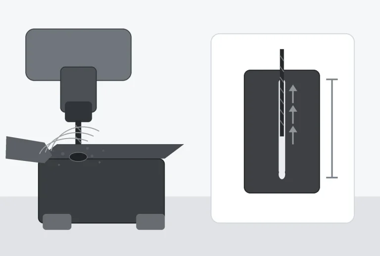
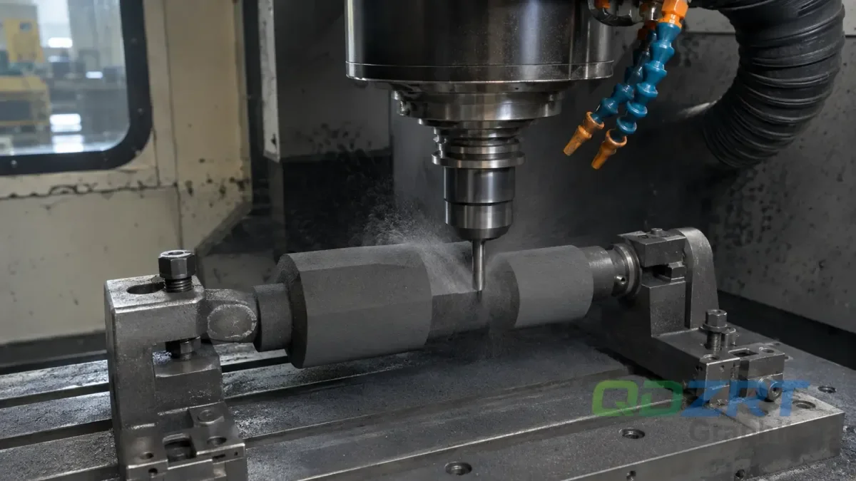
EDM graphite electrodes may require milling, drilling, profiling, slotting, and finishing. The sequence should follow the electrode shape and the features that actually need control.
The most important details are usually corner definition, rib strength, surface consistency, electrode length, mounting features, and dimensional repeatability across multiple electrodes. If the electrode is part of a repeat job, the material and machining plan should support consistent replacement parts.
If several electrodes belong to the same mold or tooling set, send the full electrode group together. It helps avoid inconsistent material or machining decisions between related parts.
Electrode machining begins with datum strategy. The holder interface or reference surfaces should be established while the block still has enough section strength. Roughing then removes bulk material without exposing fragile ribs too early. Semi-finishing stabilizes walls and leaves a controlled finishing allowance. Final passes use sharp tools, reliable extraction, and tool paths that avoid unsupported exit cuts.
The article on five keys to successful graphite machining covers the dry process, while graphite machining speeds from the shop floor explains why spindle speed and feed must be balanced rather than copied from metal. For fine electrodes, the relevant output is not only size. It includes corner definition, rib survival, surface uniformity, datum repeatability, and freedom from embedded contamination.
- Roughing: preserve supporting stock around thin features and avoid deep full-width engagement that traps dust.
- Tool selection: use geometry and coating appropriate to abrasive graphite; define a tool-life rule for critical details.
- Finishing allowance: leave enough material to remove roughing damage without forcing a heavy final pass.
- Exit strategy: support through-holes and fragile edges so the cutter does not break material away at the exit.
- Inspection: clean the electrode, establish the holder datum, and measure with a method that will not damage fine details.
- Identification: mark roughing, semi-finish, and finish electrodes so they cannot be reversed during setup.
When Wire EDM Enters the Picture
For application examples, review custom graphite parts in EDM, furnace, and semiconductor applications and the industrial uses of graphite block. These contexts help distinguish an electrode blank, a finished electrode, and a graphite component that remains in the final equipment.
Sinker EDM performs a different function: it transfers the finished electrode geometry into the conductive workpiece. Wire EDM may manufacture selected electrode features or associated metal tooling, while grinding, probing, polishing, and metrology complete other parts of the route. Each operation needs its own datum and acceptance criteria.
| Selection point | CNC milling | Wire EDM / micro-WEDM |
|---|---|---|
| Typical geometry | Three-dimensional pockets, ribs, steps, curved forms, holder interfaces, and general electrodes. | Through profiles, thin straight sections, narrow slots, or features where wire access is available. |
| Primary constraints | Tool access, abrasive wear, dust capture, chipping, workholding, and feature support. | Conductivity, thickness, wire path, flushing, speed, wire stability, debris, and machine cleanliness. |
| Decision evidence | Toolpath review, tool access, feature-risk map, trial feature, and inspection plan. | Machine capability, approved graphite grade, representative cut, kerf and surface result, and contamination-control plan. |
The selection is not simply “milling versus EDM.” It depends on electrode thickness, grade conductivity and structure, wire access, flushing, contamination control, straightness, surface requirement, production quantity, and the capability of the specific machine. A published 2026 study on low-energy EDM notes that graphite tool-electrode preparation may use wire EDM or conventional machining, while micro-manufacturing research has demonstrated graphite disk electrodes produced with micro-WEDM. These examples establish technical feasibility, not a universal replacement for milling.
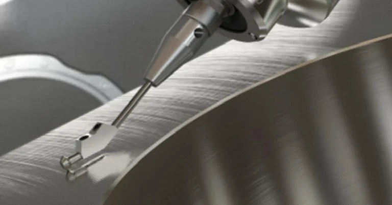
CNC milling remains the most common manufacturing route for conventional graphite electrodes because it is flexible, productive, and compatible with three-dimensional forms. Wire EDM or micro-WEDM can also be selected for particular conductive graphite electrodes when thin walls, narrow straight profiles, delicate edges, or difficult-to-mill features justify the slower and more specialized process.
The Electrode-to-Cavity Control Loop
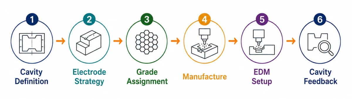
A useful EDM program closes the loop between the electrode drawing and the cavity result. The loop starts with the mold cavity requirement, converts it into electrode stages and spark-gap strategy, assigns a graphite grade, machines and inspects each electrode, records the holder datum, then returns cavity inspection data to the next electrode or technology revision. Without this loop, a cavity correction can be made in the machine while the electrode drawing remains unchanged, creating repeat-order risk.
| Control gate | Input and output | Typical owner / approver |
|---|---|---|
| Gate 1 — Cavity definition | Functional surfaces, depths, radii, texture, tolerances, workpiece material, and cavity inspection plan. | Mold owner, designer, or end user. |
| Gate 2 — Electrode strategy | Roughing/finishing stages, electrode quantity, compensation convention, holder system, and electrode IDs. | EDM shop with mold-owner approval. |
| Gate 3 — Grade assignment | Named grade or approved equivalent, supplier data, dimensions, orientation, and acceptance requirements. | Electrode supplier and EDM process owner. |
| Gate 4 — Electrode manufacture | Approved drawing, datum, machining revision, inspection result, identification, and packing. | The nominated electrode manufacturer, within a documented and approved order scope. |
| Gate 5 — EDM setup | Polarity, technology, peak current, pulse timing, gap, orbit, flushing, offsets, and stage sequence. | EDM shop or machine-process owner. |
| Gate 6 — Cavity feedback | Cavity dimensions, depth, corner condition, surface result, wear result, and approved correction history. | EDM shop with mold-owner or final-inspection approval. |
This loop is especially important when a project uses multiple electrode suppliers or when a mold returns months later for maintenance. The controlled relationship between cavity revision, electrode revision, grade, holder, and machine technology prevents an old electrode from being accepted simply because it looks similar.
Grade Selection by EDM Duty, Not Marketing Label
Terms such as premium, ultrafine, high density, and high strength are useful market descriptions, but their exact definitions vary by manufacturer. The buyer, electrode manufacturer, and EDM process owner should evaluate the selected supplier data against the actual duty. Roughing may prioritize removal rate and economic material use; finishing may prioritize uniform fine structure, edge strength, wear behavior, and the required cavity surface. As one named example, POCO EDM-2 is published as an ultrafine grade with an average particle size below 5 µm. That value describes EDM-2 and should not be applied automatically to another supplier’s “ultrafine” label.
EDM grades are published as distinct supplier families for roughing through finishing, which is why a generic “EDM graphite” description is incomplete. The order file should name the grade or define the accepted properties and equivalence review. The Mersen use recommendations also emphasize that gap, polarity, current, pulse timing, and flushing must be adjusted to the geometry and process rather than treated as one fixed setting for each graphite grade. For related drawing issues, see custom graphite part drawing review and thin walls and small holes in graphite quotations.
Spark-gap and orbit compensation belong to a controlled electrode/EDM system. They should not be embedded in an unexplained 3D file and then applied again at the machine. The drawing must state whether geometry is nominal or compensated.
EDM Electrode Drawing Package
A usable electrode package separates cavity geometry from electrode geometry. The mold or workpiece drawing defines the required cavity. The electrode drawing then records spark-gap compensation, holder datum, overburn strategy, orbit allowance where used, roughing or finishing identity, and the inspection state before EDM. These values must not be inferred from a screenshot. One controlled revision should be linked to the named graphite grade and electrode ID.
The graphite drawing-review article explains datum and feature control. The tolerance confirmation guide shows how measurement method changes the drawing decision, while common graphite machining mistakes covers grade, workholding, dust, and tool-life failures that can damage an electrode before it reaches the EDM machine.
For repeat orders, each electrode should retain a unique part number, stage identity, approved graphite grade, drawing revision, holder interface, measured critical features, and packing position. The OEM customization guide describes how this information enters a controlled order, and the manufacturer evaluation guide explains the evidence expected before production release.
Spark gap, stock allowance, particle-size class, and wear targets in this section are review categories, not published EDM settings. Actual values come from the machine technology, workpiece material, current density, flushing, polarity, cavity depth, finish requirement, and approved graphite grade.
Conclusion
EDM graphite electrodes work well when the material selection and machining route match the electrode’s job. A simple electrode may only need the right block and clean machining. A fine-detail electrode may need closer attention to grade, grain, corner protection, surface finish, and repeatability.
EDM graphite electrodes are not only consumable tooling. They are precision graphite parts, and their performance depends on both material selection and machining control.
For EDM material selection and tooling applications, see our EDM and Precision Tooling page. For drawing-based finished components, review the Custom Graphite Machined Parts page.
Frequently Asked Questions
Is finer-grain graphite always better for EDM electrodes?
No. Finer structure can support detail and finish, but the project also depends on strength, resistivity, wear behavior, electrode size, removal stage, and cost. A large roughing electrode may not benefit from the same grade used for a narrow finishing rib. The grade should be assigned by EDM duty, with roughing and finishing electrodes identified separately in the controlled order file.
Should the electrode 3D model include the spark gap?
It can, but the convention must be explicit. A nominal cavity-derived model, an electrode compensated for a fixed gap, and a model that expects machine orbit are different files. The drawing or manufacturing sheet must state the compensation basis so the same allowance is not applied twice. Machine-specific gap and orbit values remain under the EDM process owner’s control.
Why are multiple electrodes used for one cavity?
Deep or detailed cavities can consume electrode corners and length during roughing. Separate roughing, semi-finishing, and finishing electrodes protect the final geometry and allow each burn stage to use suitable technology. The number depends on depth, projected area, workpiece material, finish target, flushing, and acceptable wear—not simply on cavity size.
How are thin EDM ribs protected during graphite machining?
For thin-rib electrodes, the manufacturing plan may preserve supporting stock until a late stage, require graphite-suitable sharp tools, control exit direction, limit handling, and inspect the rib from a stable datum. These controls must be confirmed with the selected manufacturer rather than assumed. The selected grade must support the feature, and finished electrodes can be separated and supported in packing so a rib that survives machining is not lost in transport.
Can graphite electrodes produce a mirror-finish cavity?
Certain graphite grades and modern EDM technologies can achieve very fine surfaces, but “mirror finish” is not a material-only promise. Workpiece alloy, generator technology, pulse settings, flushing, electrode structure, wear, orbit, and post-EDM polishing all influence the result. A representative trial and a defined measurement or reference surface are more reliable than a generic finish claim.
What inspection belongs on a finished graphite electrode?
A finished-electrode inspection report may identify the grade, electrode ID, drawing revision, holder or reference datum, critical dimensions, rib and edge condition, flushing features, and compensated geometry. Measurement should not damage fine features. Photographs, identification, and dimensional reports should be requested only when the selected manufacturer confirms the required scope and acceptance method in the order.
What files are needed to quote an EDM electrode set?
Send the cavity and electrode models if available, 2D drawings, workpiece material, EDM machine/technology context, roughing and finish stages, compensation convention, holder interface, quantity, required grade or performance objective, and inspection scope. When the strategy is not yet fixed, the inquiry should request a documented grade and manufacturability review while the EDM shop retains final control of burn technology.
References & Sources
- Evaluation of Graphite as Tool Electrode Material in Low-Energy EDM Processes — Supports the use of conventional machining or wire EDM in graphite tool-electrode preparation within the study context.
- Micro Electrochemical Machining of Array Micro-Grooves Using In-Situ Disk Electrode Fabricated by Micro-WEDM — Research example of a graphite disk electrode fabricated by micro-WEDM for a specific micro-manufacturing route.
- NIST Dimensional Metrology — Uncertainty and Statistics — General measurement-uncertainty and assurance concepts only; not evidence of graphite-specific tolerance capability.
Discuss an EDM Graphite Electrode Project With QDZRT Graphite
Start the inquiry through the QDZRT Graphite contact page with the compensation convention, holder interface, workpiece material, EDM stage, quantity, grade requirement, and inspection points. After we reply, send the current controlled electrode or cavity files by email or another agreed secure channel. The inquiry should separate grade selection, electrode manufacturability, inspection scope, and machine-specific burn technology so each responsibility is confirmed by the appropriate party.