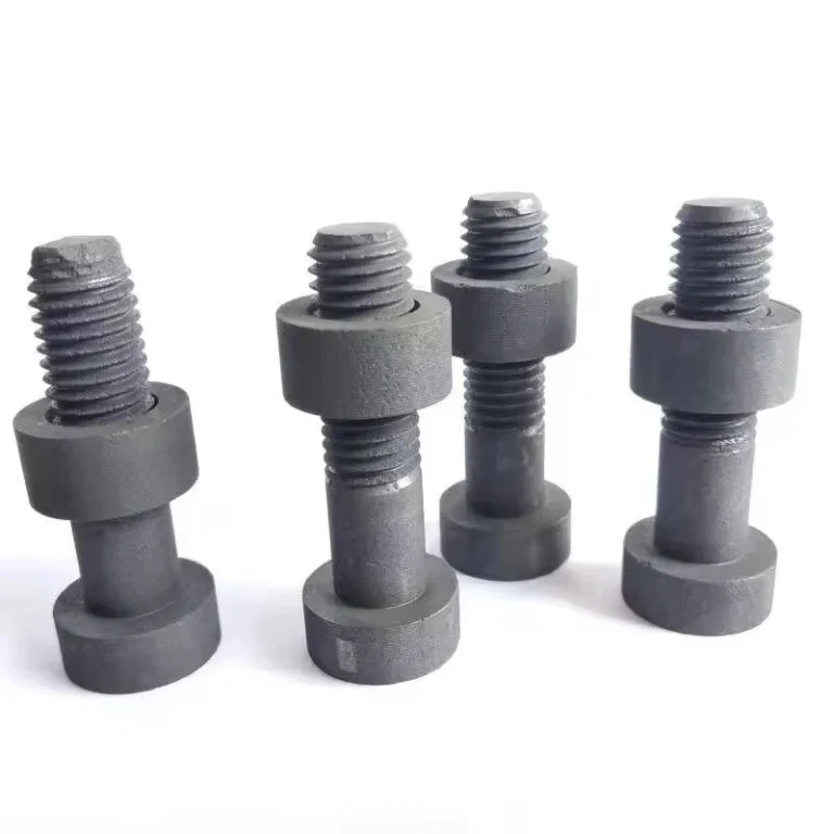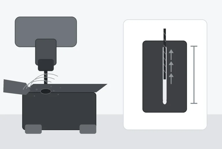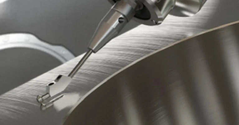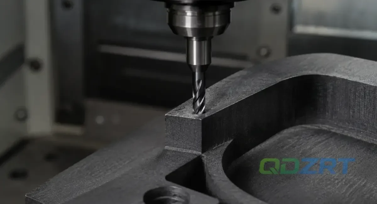
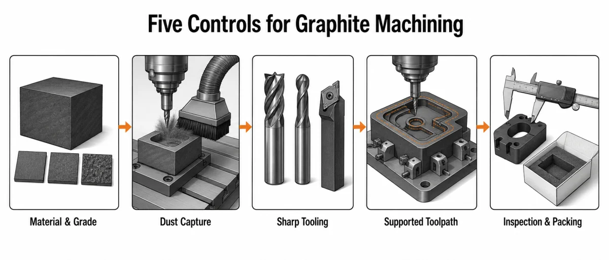
Graphite machining works best when the process is planned around the material. Graphite can be machined into detailed industrial components, but its porosity, abrasive character, brittle edges and dry-cutting dust require controls that differ from a conventional metal program.
| Primary control | Project input or process check | Why it matters |
|---|---|---|
| 1. Material & grade | Confirm material identity, forming route, supplier grade, property sheet, blank condition and application requirements. | The drawing defines geometry, while the approved material data define the properties that must remain after machining. |
| 2. Dust capture | Plan local extraction, enclosure cleaning, filter/duct checks and any required workplace exposure assessment. | Graphite dust can affect the machine, part cleanliness, measurement and worker exposure. |
| 3. Sharp tooling | Select tool material and edge geometry for the named grade, feature, run length and surface requirement. | Graphite is abrasive; tool wear can appear as chipping, dimensional drift or surface damage. |
| 4. Supported toolpath | Sequence roughing, finishing, workholding and temporary support around thin or fragile features. | A feature can be geometrically machinable but still fail if it becomes unsupported too early. |
| 5. Inspection & packing | Define datums, measurement method, free-state support, cleaning level and protection of finished features. | The part must remain measurable, clean and undamaged after it leaves the machine. |
For a drawing-based project, the approved material data, controlled drawing, quotation, inspection plan and packing requirements should agree before production. This keeps a convenient machining choice from replacing the application requirement.
Material choice affects tool wear, dust behavior, edge strength, support strategy and inspection response, so changes in one part of the process should be checked against the rest of the machining plan.
1. Control Material Condition and Grade
Keep the Material Dry
Graphite is commonly machined dry. Liquid coolant can create slurry, carry fine graphite particles into unwanted areas, and affect material cleanliness. If the graphite stock has absorbed moisture during storage or handling, that moisture can also make cutting less predictable.
Dry material helps chips and dust leave the cut more cleanly. Wet or contaminated material can pack inside slots, holes, saw cuts, and pockets, forcing the tool to recut the same material instead of clearing it.
Because graphite has an open pore structure, storage and handling should prevent moisture, oil, metal particles, packaging fibres and residue from unrelated operations from entering the surface. The required controls depend on the application: ordinary furnace hardware, electrical parts, vacuum components and semiconductor-related parts do not necessarily have the same cleanliness acceptance.
- Storage: Keep blocks, plates, and rods on clean supports in a dry area rather than directly on concrete or near coolant mist.
- Blank preparation: Remove loose packaging dust and verify the material identity before sawing or rough machining.
- Workholding: Use clean jaws, soft interfaces, or dedicated fixtures so oil and metal chips are not pressed into graphite surfaces.
- In-process cleaning: Extract dust close to the cut and clear holes or pockets before measurement, without driving particles deeper into narrow features.
- Final cleaning: Match the cleaning method to the application, purity requirement, part geometry, and any later coating or impregnation process.
A drawing-based order often begins with a suitable graphite block blank. Its dimensions must leave enough machining allowance while avoiding unnecessary stock removal. The material-selection guidance described in the graphite block OEM sourcing guide is also relevant when blank size, forming method, and finished geometry must be coordinated.
Material condition and the post-machining cleaning route should be agreed before production when the part has a defined cleanliness, coating, impregnation, electrical, thermal, sealing or vacuum requirement.
Select the Grade From the Application and Approved Data
Graphite grades are not interchangeable. Grain size, density, hardness, strength, porosity, purity, and electrical or thermal behavior can change from one grade to another. Those differences affect both machining and final performance.
Fine details usually need a finer grade. High-temperature fixtures may need another material selection. Electrical or sealing applications may require different properties again. The part drawing gives the shape, but the application helps define the material.
Forming route matters as well. Molded, extruded, vibration-molded, and isostatically pressed graphites can have different property distributions and available block sizes. Extruded material often has a more evident forming direction, while isostatic material is selected when more uniform properties in different directions are important. That distinction affects how a blank is oriented, where a thin wall is placed, and how thermal or electrical performance is interpreted.
Published data remain grade-specific. During quotation, QDZRT Graphite confirms the required product form, grade and properties instead of treating another manufacturer’s catalog value as a universal graphite class.
| RFQ field | Information to record | Approval boundary |
|---|---|---|
| Supplier and exact grade | Manufacturer, grade name, data-sheet revision and any approved equivalent. | Trade names and grade families are not interchangeable across suppliers. |
| Forming route and orientation | Molded, extruded, vibration-molded or isostatic route; relevant blank orientation. | Directional properties and available stock size may affect feature placement. |
| Particle or grain metric | Reported value, whether average/maximum/other, units and supplier definition. | A “5 µm grade” is incomplete without the metric and named grade. |
| Bulk density and mechanical properties | Density, hardness, flexural/compressive strength and stated methods or data-sheet basis. | Density alone does not prove edge strength or machinability. |
| Purity and application limits | Carbon basis, ash or trace-element limits, atmosphere, temperature, coating or impregnation requirements. | Purity, ash and element-specific limits must not be treated as the same measurement. |
| Blank size and finished geometry | Available stock size, skin condition, orientation, datum plan and critical thin features. | The machining route must be checked against the actual blank, not a generic grade table. |
The purchase specification should name the material and the properties that matter to the application. A supplier data sheet describes that grade; it is not a blanket capability statement for other grades or suppliers.
For EDM electrodes, the material-selection approach is explained in our EDM and precision tooling solution and the article on choosing graphite block for EDM electrodes. Semiconductor-related fixtures, susceptors, shields, and support parts may add purity, coating, impregnation, and particle-control requirements; those issues are discussed in the guide to graphite machined parts for semiconductor equipment.
Start grade selection with service requirements and feature integrity, then check machinability, stock availability, and inspection needs. The easiest grade to cut is not automatically the right material for the finished component.
2. Capture Dust and Protect Cleanliness
Dry graphite machining produces fine dust. That dust should be controlled because it can affect the machine, the work area, the part surface, and inspection reliability. Dust also becomes more important when the part has small holes, grooves, pockets, or clean functional faces.
Dust control begins during machining, not after it. Cleaner cutting, measurement, and packing steps make it easier to deliver a usable graphite part.
Occupational exposure controls are set by the actual material, applicable local regulations and an industrial-hygiene assessment. The CDC/NIOSH Pocket Guide has separate entries for natural graphite and synthetic graphite. The 2.5 mg/m³ respirable REL shown for natural graphite must not be transferred to synthetic graphite machining. The synthetic-graphite entry lists OSHA particulate limits and NIOSH Methods 0500 and 0600, while the governing workplace limit and control plan still depend on jurisdiction and assessment.
| Control point | Process control | Verification and record |
|---|---|---|
| At the cutter | Position local capture close enough to collect dust without interfering with the tool, fixture or programmed motion. | Document hood/nozzle position and verify capture performance by the approved airflow or industrial-hygiene method. Visible dust is only a warning sign. |
| Enclosure and machine surfaces | Use cleanable surfaces and a housekeeping plan for covers, datums, sensors and electrical areas. | Record inspection and cleaning intervals; a visibly clean surface does not by itself prove respirable-dust control. |
| Filters and ducts | Monitor the parameter specified by the extraction-system supplier, such as pressure drop or airflow, and maintain filters and ducts. | Retain readings, alarm limits, filter changes and corrective actions under the maintenance plan. |
| Part cleaning | Use controlled vacuum or another application-compatible method; avoid spreading conductive dust with uncontrolled shop air. | Check holes, grooves, threads and datums before measurement using the agreed cleanliness method. |
| Workplace exposure | Apply the correct material classification, local limits, risk assessment, engineering controls and PPE program. | Use exposure measurement where required; do not substitute plume visibility or housekeeping for industrial-hygiene evidence. |
Packed dust can alter hole depth, datum seating, and surface inspection. Related mechanisms are reviewed in common graphite machining mistakes and graphite machining challenges.
3. Use Sharp Tooling and Protect Edges
Because graphite is abrasive, tool condition directly affects edge damage, finish, and batch repeatability; a dull tool does more than cut slowly.
Sharp tooling is especially important when the part has thin walls, small holes, ribs, slots, or edges that must stay clean. If a sharp corner is not functional, a small chamfer may make the part more practical without changing its use.
Tool material is selected according to grade hardness, geometry, surface requirement, and production quantity. Sharp uncoated carbide can be suitable for prototypes and many general operations. Diamond-coated carbide extends life in abrasive cutting when coating thickness and edge geometry remain compatible with the feature. Polycrystalline diamond tooling can be justified for stable, repeat production, although tool cost, available geometry, runout control, and repair strategy must be considered.
Toyo Tanso identifies dry machining as suitable for graphite and states that machining dust requires dust-collection equipment. Mersen lists micro-grain tungsten carbide and diamond among tools for its EDM graphites. These sources support the general route only; the final cutter, coating, edge preparation and replacement limit still depend on the named grade, geometry, machine and production quantity.
Tool changes are tied to edge breakout, dimensional drift, surface texture, hole size, and protected-corner condition. Grain size and strength also relate directly to fine-detail machinability.
- Edge chipping increases: Check cutting-edge wear, excessive engagement, unsupported exit edges, and blank defects.
- Hole size drifts: Check tool wear, runout, dust evacuation, peck strategy, and whether the hole is measured clean.
- Surface becomes glazed or crushed: Check whether a dull edge is rubbing instead of cutting.
- Thin ribs vibrate: Reduce cutting force, retain support longer, shorten tool overhang, and revise the feature sequence.
- Batch repeatability declines: Establish a tool-life limit tied to measured features rather than waiting for visible tool failure.
Cutting conditions are not copied from a metal program or another graphite grade without review. Tool diameter, flute count, engagement, machine rigidity, extraction, feature depth and material grade are evaluated together. Our graphite machining process-control article explains how these inputs are approved for production.
Functional sharp edges should be identified on the controlled drawing. Nonfunctional edges may use a specified chamfer or radius only when the drawing and application permit it; no universal edge-break value applies to every graphite part.
4. Support the Part Through Toolpath and Workholding
Plan the Toolpath Around Graphite
Graphite toolpaths should avoid creating weak unsupported sections too early. Pockets, islands, ribs, and thin features need a cutting sequence that keeps the part stable while material is removed.
Our toolpath review protects unsupported walls and edges by retaining sufficient support during stock removal. Pocket sequence, tool access and final passes are approved for the actual wall thickness, graphite grade and protected surfaces.
We control engagement around thin walls and corners, select entry and exit locations that protect unsupported edges, and review reach, extraction, corner radius and inspection access for deep pockets. The approved route records these decisions for the drawing revision.
| Feature or stage | Project-specific inputs | Toolpath and support review |
|---|---|---|
| Sawed blank and skin removal | Actual blank dimensions, saw tolerance, grade, forming direction, skin condition and datum plan. | Set machining allowance from the received blank and required finished surfaces; do not use one allowance per face for every part. |
| Roughing and finishing stock | Part size, stability, sequence, tool condition, measurement stage and any rest/thermal-stabilisation requirement. | Define stock by the approved process plan and keep it uniform where that improves finishing control. |
| Small or deep holes | Hole diameter and depth, bottom form, breakthrough condition, tool stiffness, evacuation path and inspection access. | Review pecking, support, tool reach and cleaning; a depth ratio alone is not an acceptance limit. |
| Thin walls, ribs and rings | Wall height, length, local section, grade strength, clamp location and free-state requirement. | Retain surrounding stock or temporary support as needed and release support in a controlled sequence. |
| Pockets and internal corners | Tool diameter, corner radius, depth, entry/exit location, dust path and protected surfaces. | Avoid creating unsupported exits or closed dust paths; confirm that the feature can be inspected. |
| Edges and breakouts | Functional status, adjacent feature, grain structure, exit direction, handling and packing risk. | Specify a chamfer/radius only when approved; otherwise protect the required sharp edge through machining and handling. |
The process plan should record the values selected for the actual grade, blank, feature, tool and inspection method. Numbers from a previous job are useful only after confirming that the geometry, material and acceptance conditions are comparable.
A clear drawing identifies which dimensions share a datum, which edges are functional, which surfaces may receive a coating, and whether tolerances apply before or after post-processing. Our article on graphite drawing review and tolerances explains why a graphite part needs a different review from a metal part. The effect of narrow ribs, small bores, and deep grooves on manufacturing is covered in thin-wall and small-hole graphite part planning.
The drawing review should identify pockets, ribs, thin walls, functional surfaces and protected edges before the setup and toolpath are released. This turns a general warning into a controlled manufacturing input.
Design Workholding and Support Before Cutting
Graphite can be held securely without being squeezed like a ductile metal. Excessive jaw force may mark a surface, crush local material, or introduce a crack that appears only after more stock is removed. Too little force allows movement and vibration. Workholding therefore distributes load over suitable areas, protects finished surfaces, and keeps clamps away from regions that will become thin.
Support is retained as long as possible around ribs, windows, slots, and thin rings. A sacrificial bridge can stabilize a feature during roughing and be removed near the end. A thin flange may be finished while the surrounding stock still carries the clamping load. For parts with multiple critical faces, the setup sequence protects established datums rather than repeatedly gripping the finished geometry.
Application-dependent fixture choices are illustrated in custom graphite machined parts and the custom graphite parts manufacturer guide.
5. Inspect, Clean, and Pack Against the Real Failure Modes
Match Tolerances to Inspection and Function
A tolerance is useful only when the feature can be machined, cleaned, accessed and measured consistently. The same numerical tolerance can represent very different difficulty on a short open diameter, a deep blind bore, a thin unsupported wall or a large flat face. The review should therefore connect the datum structure, feature relationship, material grade, measurement method, surface condition and inspection stage before capability is accepted.
Machine accuracy alone does not guarantee part accuracy. Thermal behavior, tool wear and process effects can change accuracy over time. Our capability review therefore also covers graphite grade, abrasive wear, dust, contact force, support and the approved measurement plan.
| Feature category | Required capability evidence | Inspection plan fields |
|---|---|---|
| External length, width or step | Named grade, size range, setup, tool condition and demonstrated process result for a comparable feature. | Instrument, resolution, datum, temperature, sampling and acceptance rule. |
| Bore, pin or internal diameter | Diameter/depth, roundness requirement, tool access, cleaning route and gauge-force sensitivity. | Gauge type, depth locations, roundness or cylindricity method and debris check. |
| Flatness or parallelism | Surface size, thickness, support/free-state condition, material orientation and release from clamps. | Support points, measurement map, stabilisation time and whether inspection is free-state or fixtured. |
| Hole position or feature relationship | Controlled datum scheme, setup count and coordinate system aligned to the drawing. | CMM/optical/fixture method, datum simulation, sampling and reporting format. |
| Thin wall, rib or fragile edge | Local section, height/length, contact-force limit, support history and handling plan. | Non-contact or low-force method where needed, plus post-unclamping and pre-packing checks. |
| Batch capability | Comparable part evidence, tool-life rule, offset strategy and measurement frequency. | First-off, in-process and final sampling with defined reaction to drift. |
Specific tolerances should be quoted only after the grade, overall size, feature geometry, quantity, equipment, setup and inspection method are known. Where capability evidence is required, the quotation or approved quality plan should state the comparable feature, measurement conditions and acceptance record.
Over-tolerancing every dimension increases setups, finishing passes, inspection time, tool-change frequency, and scrap risk without necessarily improving function. Under-defining datums creates a different problem because the part may pass one interpretation and fail another. The article on confirming custom graphite part tolerances explains the drawing information needed for a reliable review.
A quotation package normally includes the drawing revision, material requirement, quantity, application, critical features, inspection standard, cleaning level, and packing expectation. Use the graphite project contact page to start the inquiry and summarize the key requirements. After we reply, send the controlled drawing and other project files by email or another agreed secure channel.
Clean, Handle, and Pack the Finished Part
Machining is complete only after the part has been cleaned, inspected, protected, and packed. Loose dust is removed from open surfaces, holes, channels, threads, and recesses using a controlled method that matches the cleanliness requirement. Parts intended for vacuum, semiconductor-related, electrical, thermal, or coating service may need a more specific cleaning and handling route than ordinary furnace fixtures.
Handling avoids direct impact and concentrated pressure. Thin rings are supported around their circumference. Long rods are prevented from bending under their own weight or under packaging straps. Small precision parts are separated so that hard edges cannot strike one another. Finished datums and sealing faces receive clean protective interfaces rather than abrasive loose filler.
The broader application range can be reviewed in our custom graphite parts application article, while related graphite material and finished-product categories are organized under the Graphite Machining knowledge section.
Recognize Failure Patterns Before They Repeat
- Repeated corner breakout: Review grain size, exit direction, tool wear, edge allowance, clamping, and whether the drawing permits an edge break.
- Dimensions drift through the batch: Review abrasive tool wear, machine warm-up, datum cleanliness, offset strategy, and measurement frequency.
- Blind holes measure shallow: Confirm dust removal, drill point allowance, depth reference, probe access, and whether loose powder remains at the bottom.
- Thin walls crack after unclamping: Review clamp load, wall sequence, remaining support, local material defects, and free-state inspection.
- Surface contamination appears after cleaning: Trace fixture materials, gloves, packaging, compressed-air quality, mixed-workshop dust, and any prior wet operation.
- Parts pass inspection but arrive damaged: Review separators, restraint, box rigidity, drop exposure, stacking direction, and protection of high-risk features.
Conclusion
Successful graphite machining comes from five connected controls: the approved material and grade, effective dust capture, sharp tooling, a supported toolpath and workholding plan, and inspection and packing that protect the finished function. Dry storage, cleaning and failure review sit within those controls.
A graphite component is complete only when the correct material has been machined, measured, cleaned and protected under an approved route. Accuracy at the machine does not compensate for an unsuitable grade, unverified dust control, damaged edges or ambiguous inspection.
For drawing-based finished graphite components, review our Custom Graphite Machined Parts page. For graphite blanks and stock material, see the Graphite Block page.
A useful quotation package identifies the application, grade or required properties, drawing revision, critical dimensions, protected edges, quantity, inspection method, cleaning level and packing constraints. Those inputs let QDZRT Graphite review whether the requested grade, geometry, inspection and handling route fit together before the order is released.
Frequently Asked Questions About Graphite Machining
Is graphite normally machined dry or with coolant?
Most graphite milling, turning, drilling, and sawing is performed dry with local dust extraction. Dry cutting avoids creating a graphite slurry and simplifies cleaning of holes, pockets, and machine surfaces. A specialized wet process may be possible, but it requires a defined fluid, contamination assessment, drying method, waste route, and acceptance criteria. For clean, electrical, thermal, vacuum, sealing, or semiconductor-related parts, the effect of any fluid on pores and later processing must be reviewed before machining.
Which graphite grade is easiest to machine?
There is no single easiest grade for every part. A softer general-purpose graphite may cut quickly but may not hold a narrow rib or fine edge. A dense ultra-fine grade can support detail but may be harder on tools and more expensive. The review should cover grain size or particle metric, density, strength, hardness, porosity, forming direction, purity and the final application. The best grade is the one that provides sufficient feature integrity and service performance with a stable manufacturing route.
Can graphite hold tight CNC tolerances?
Graphite can be machined to close tolerances when the grade, geometry, tool condition, setup, dust control, and inspection method are compatible. Difficulty rises for deep small holes, high thin walls, large flat surfaces, fragile sharp edges, and dimensions that depend on several setups. A tolerance must also be measurable without damaging or distorting the part. Capability should be confirmed feature by feature rather than applying one tolerance statement to every dimension on every graphite component.
Why do graphite edges chip during machining?
Edge chipping can result from a coarse or unsuitable grade, worn tooling, excessive engagement, poor exit direction, vibration, clamp pressure, unsupported geometry, or impact during handling. The fracture location and repetition pattern help identify the mechanism. A small controlled chamfer often improves reliability when the edge is not functional. Functional sharp edges require a finer review of material, toolpath, tool condition, support, inspection, and packaging because the machining operation is only one point where damage can occur.
What information is needed for a custom graphite machining quotation?
The quotation package normally includes a controlled 2D drawing, 3D model when available, part number, revision, quantity, annual demand, graphite grade or required material properties, application, operating temperature and atmosphere, critical tolerances, protected surfaces, coating or impregnation requirements, inspection standard, cleaning level, and packing expectation. Marking functional edges and datums reduces ambiguity. When a grade is not fixed, property targets and service conditions allow candidate materials to be screened before quotation and sample approval.
How is graphite dust removed from holes and pockets?
Dust is captured near the cutting zone and removed using controlled vacuum and an application-compatible cleaning method. Uncontrolled shop-air blowing can spread conductive dust through the machine or drive particles into other areas. Blind holes, threads, grooves, and narrow channels are checked before dimensional inspection because packed material can alter depth and diameter readings. The final cleaning route depends on part geometry, required cleanliness, purity, later coating, and whether the component will operate in a vacuum or contamination-sensitive environment.
Are diamond tools always necessary for graphite?
No. Sharp carbide can be suitable for prototypes, short runs, and many general graphite operations. Diamond-coated carbide or PCD becomes more attractive when abrasive wear, batch quantity, fine detail, dimensional stability, and tool-change cost justify the investment. Tool geometry and coating condition still matter; a long-life tool with an unsuitable edge can damage a thin feature. Tooling should be selected by grade, feature, tolerance, finish, machine capability and production volume rather than using one tool material for every job.
References & Sources
- CDC/NIOSH, NIOSH Pocket Guide: Graphite (Natural). Natural-graphite exposure information; not applied to synthetic graphite.
- CDC/NIOSH, NIOSH Pocket Guide: Graphite (Synthetic). Synthetic-graphite classification, OSHA particulate limits and Methods 0500/0600 context.
- NIST, Improving CNC Machining Accuracy Through Thermal Model-Based Control. General CNC thermal-error and tool-wear context only; not graphite tolerance evidence.