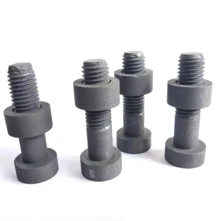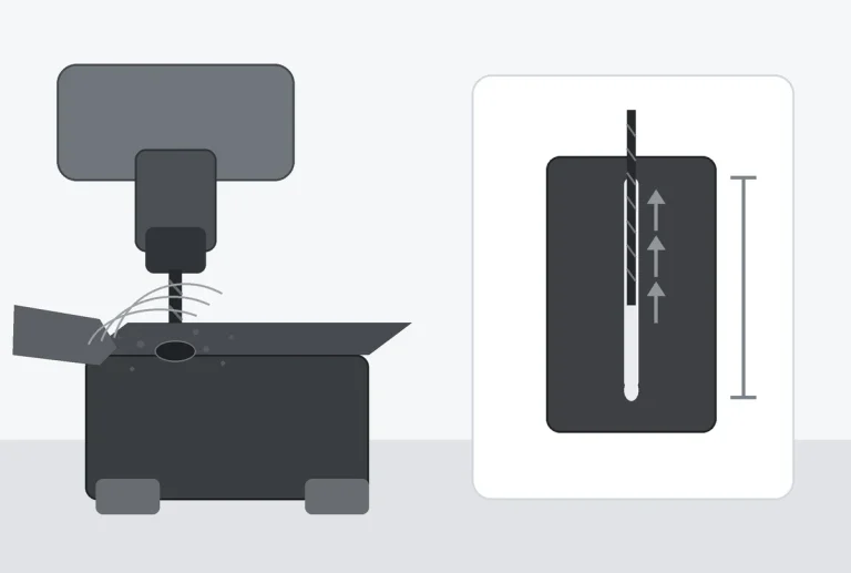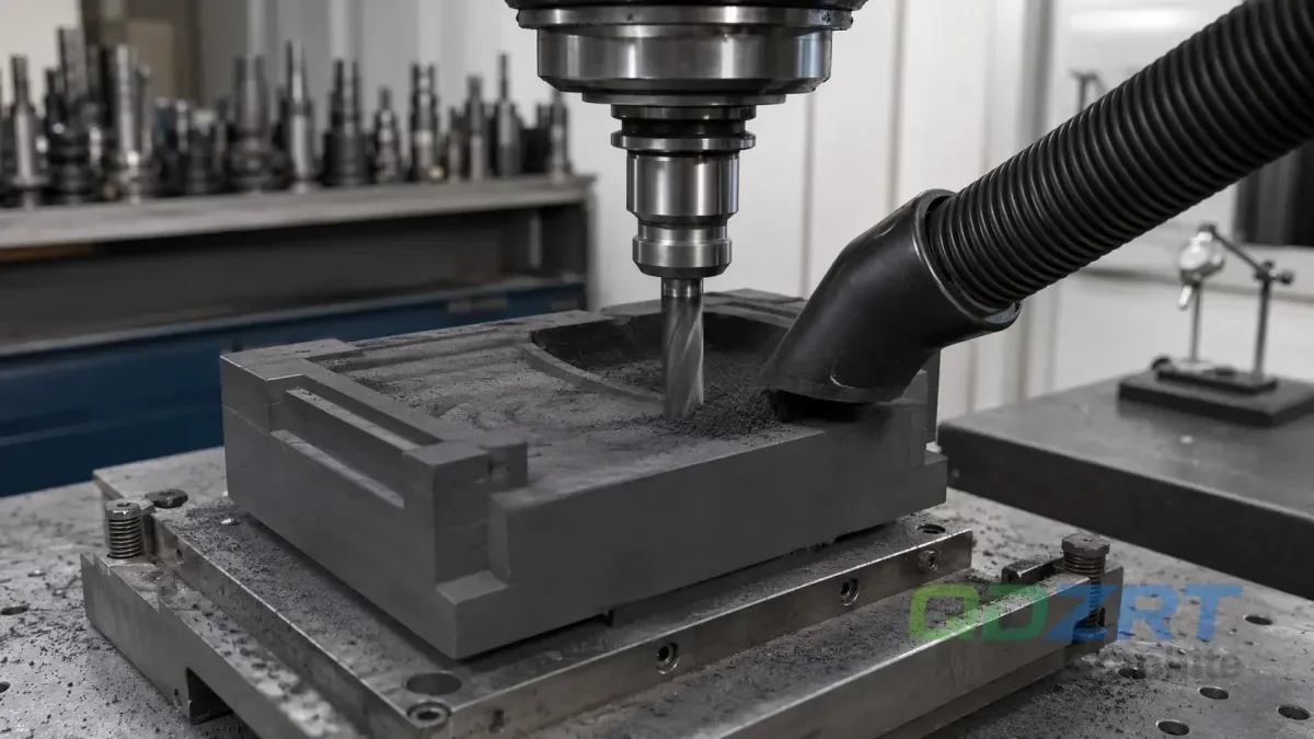
A graphite machining defect is easiest to solve when the visible symptom is separated from the stage that created it. A chipped edge may originate in the grade, unsupported geometry, tool condition, cleaning method, or packing restraint. A drifting diameter may come from wear, dust on a datum, thermal change, runout, or the measurement method. Treating the first plausible explanation as the root cause often produces a temporary fix and a repeat failure.
When a graphite part fails inspection, start with the defect pattern and preserve the parts and records before changing the process. Find where the first nonconforming condition appeared, test the smallest credible set of causes, and approve corrective action only after the result is verified across requirement, material, geometry, machining, inspection, and delivery.
| Diagnostic item | Evidence to preserve | Why it narrows the investigation |
|---|---|---|
| Defect pattern | Photographs, location on the part, orientation, affected quantity, first-good and first-bad pieces, and whether the pattern is random or progressive. | A repeated location suggests geometry, support, or tool-path exposure; progressive change suggests wear, contamination, thermal movement, or measurement drift. |
| Material identity | Exact supplier grade, forming route, lot, blank orientation, data-sheet revision, and any coating or impregnation. | Graphites with similar appearance or density can differ in pore structure, particle metric, strength, hardness, resistivity, and directional behavior. |
| Process history | Machine, fixture, program revision, tool ID, tool life, extraction condition, cleaning sequence, operator, and interruption history. | A defect that begins after a tool change, filter loading event, setup change, or restart should not be diagnosed as a material problem without evidence. |
| Measurement record | Datum preparation, instrument, contact force, temperature, support condition, calibration status, and raw readings rather than only pass/fail. | Dust, unsupported walls, excessive contact force, or a changed datum can create apparent dimensional failure even when the cut did not change. |
| Post-machining handling | Cleaning method, inspection handling, tray or separator, package orientation, shock evidence, and condition on arrival. | A part can leave the machine conforming and be damaged later; the corrective action must target the stage where the defect first appears. |
Published values can support a hypothesis only when they remain attached to the named material and context. For example, POCO’s EDM-2 page identifies a specific EDM grade; the NIOSH synthetic-graphite entry and the separate natural-graphite entry describe different occupational contexts. None of these sources proves the cause of a particular chipped edge, size drift, or dust event without project evidence.
Begin with three questions: What changed, where did it first become visible, and what observation would disprove the leading explanation? The goal is not a long cause list but a cause that explains the defect’s location, timing, quantity, and direction.
Do not erase the failure pattern during the first response. Keep representative failed parts, nearby conforming parts, the tool if wear is suspected, inspection records, setup notes, cleaning records, and original packaging; reworking everything can remove the marks that distinguish machining damage from later handling.
Dimensional conformity is only one layer of acceptance. A part can match the drawing and still fail because the grade, pore condition, edge state, cleanliness, orientation, or functional surface is wrong. Conversely, a suspicious measurement may be caused by dust or support rather than an actual machining error.
Defect 1: Chipped Edges, Breakout, or Missing Corners
Record the chip shape before deciding that graphite is simply “too brittle.” A clean local corner loss, a rough breakout at a hole exit, repeated damage on one side of a rib, and random handling chips are different patterns. Their location relative to the tool exit, fixture support, material orientation, and package restraint is often more useful than the overall chip size.
Likely causes include a grade that does not support the detail, insufficient backing at tool exit, concentrated clamping load, a worn or unsuitable cutting edge, tool-path sequencing that leaves a feature unsupported, aggressive cleaning, or contact during inspection and packing. More than one cause may be active, but each should be tied to an observable pattern.
Do not default to “use a finer grade” or “reduce the feed.” Compare conforming and failed pieces from the same lot, inspect the fracture origin, check whether damage follows a machine direction or handling point, and confirm whether the chip existed before cleaning. A change that does not match the failure pattern is a trial, not a proven correction.
For a chipping investigation, mark every functional edge on the drawing and classify the observed damage as entry breakout, exit breakout, corner loss, wall fracture, cleaning damage, or transit damage. Record the tool path direction, backing condition, clamping position, and first operation after which the defect can be seen. This creates a traceable boundary between geometry, machining, and handling.
Material identity should also be checked before the process is changed. The graphite block buying mistakes guide explains why appearance and nominal density do not establish equivalence, while the graphite block OEM sourcing article shows how grade identity, blank orientation, and machining allowance can be recorded. These references help define the evidence set; they do not replace fracture-pattern review on the actual part.
Evidence Package for a Chipping Investigation
- Defect map: mark every damaged edge on a drawing or photograph, including the machining direction and whether the defect is at tool entry, tool exit, an unsupported span, or a handling contact point.
- Part sequence: retain the first conforming part, the first failed part, and representative later parts so a progressive tool or setup change can be separated from random damage.
- Material record: preserve the exact grade, lot, blank orientation, supplier data, and any coating, impregnation, or prior heat-treatment information.
- Process evidence: record the fixture, support, program revision, tool ID, tool-life point, extraction condition, cleaning step, and the operation after which the defect first appears.
- Acceptance boundary: define the functional edge, permitted edge break, inspection method, magnification where relevant, and whether repair or blending is allowed.
Defect 2: Diameter, Slot, or Profile Drift Across a Batch
A drifting feature is a trend, not a single out-of-tolerance reading. Plot the actual values in production order and identify whether the change is gradual, step-like, cyclic, or isolated. A gradual trend can indicate tool wear or filter loading; a step change can follow a tool, offset, fixture, program, or measurement change; random scatter may point to unstable support, dust on datums, or inconsistent measurement.
Separate cutting variation from measurement variation before changing offsets. Reclean the datum, repeat the reading with the same support and contact force, and compare another instrument or method where practical. Thin graphite features can move under contact, and dust trapped between the part and fixture or between the part and gauge can shift the result.
The investigation should define the feature trend, the tool-life position, the measurement sequence, and the exact point at which control was lost. Replacing a tool may restore size, but it does not prove tool wear was the only cause if the datum, runout, fixture, or inspection method changed at the same time.
Start with a time-ordered record containing part number, cavity or fixture position, tool ID, offset, machine interruption, extraction status, measured value, instrument, and inspector. Add the first-off result after every controlled change. This allows a correction to be linked to an observable response rather than to a general belief about graphite.
For preventive process controls, the successful graphite machining guide covers the connected machining route and the graphite machining challenges article describes common constraints. In a defect investigation, those topics are possible causes; the corrective action still needs a measured trend, change history and evidence that the process returned to control without creating another defect.
- Trend chart: plot actual values in production order and mark tool changes, offset changes, stops, filter service, fixture changes, and inspection handoffs.
- Tool history: record tool material, geometry, edge condition, cutting exposure, runout check, and whether the failure begins at a consistent tool-life point.
- Datum and support: verify that contact surfaces are clean, the part is supported in the same state, and the fixture has not shifted or concentrated load on a fragile feature.
- Measurement method: record instrument, contact force, temperature, calibration status, operator, repeated readings, and any difference between free-state and restrained-state measurement.
- Verification run: after one controlled correction, inspect the first part and an agreed short sequence before releasing the remaining lot.
Defect 3: Rough, Pitted, or Uneven Functional Surfaces
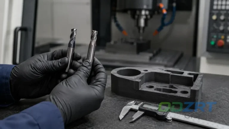
A rough or uneven surface should be described by pattern and location rather than by a single adjective. Distinguish torn-looking pits, open pores, parallel tool marks, local edge pullout, dust-packed recesses, and a general loss of detail. The pattern may follow the material structure, the cutting direction, a worn edge, poor dust evacuation, or the geometry of the feature.
Surface appearance becomes a functional issue when the area is a sealing land, electrical contact, EDM detail, vacuum surface, coating interface, or location where particles cannot be tolerated. A surface that is acceptable on a support block may be unacceptable on a narrow land or semiconductor-related fixture even when the dimensional reading is correct.
Preserve the part before polishing, blasting, wiping, or aggressive cleaning. Photograph the surface under consistent lighting and magnification, mark tool direction, and compare the first and last parts made with the same tool before rework removes the evidence.
Material structure is one possible contributor, but particle or grain size should not be used as a universal explanation. Supplier data may report an average, maximum, or proprietary metric, and the actual result also depends on strength, hardness, pore distribution, orientation, tool edge, support, and the required surface function. The investigation should connect the named grade to the observed pattern rather than to a generic “fine” or “coarse” label.
For EDM-related features, the graphite block selection guide for EDM electrodes helps distinguish grade-selection questions from machining evidence, and the EDM and precision tooling solution provides the application context. A rough surface on a finished part still requires a local pattern review, tool and cleaning history, and confirmation that the selected material was the material actually machined.
| Observed surface pattern | Likely cause groups | Evidence to collect | Controlled confirmation |
|---|---|---|---|
| Parallel ridges or periodic waviness | Tool runout, edge wear, vibration, unstable support, or a repeated tool-path event. | Tool marks under consistent lighting, tool ID, runout check, fixture contact map, program position, and part sequence. | Change one verified cause at a time and compare the same feature on a short confirmation run. |
| Local pits or particle pullout | Material structure, tool exit direction, unsupported edge, contamination, or cleaning damage. | Grade and lot, fracture location, machining direction, pre-cleaning photograph, nearby conforming area, and cleaning method. | Compare another part from the same lot before and after the suspect operation; do not substitute a different grade and process simultaneously. |
| Dust-packed holes or recesses | Insufficient evacuation, filter loading, recutting fines, unsuitable cleaning direction, or inaccessible geometry. | Extraction condition, filter status, tool-path sequence, hole depth, cleaning record, and before/after photographs. | Verify capture and cleaning on a representative feature and confirm that the method does not drive particles deeper. |
| Uneven sealing or contact land | Datum error, face support, local chipping, surface waviness, embedded particles, or wrong grade condition. | Flatness or profile method, datum preparation, contact pattern, surface image, material identity, and free-state support. | Repeat the measurement after controlled cleaning and support, then verify the corrected process on the same functional surface. |
| Detail loss on EDM or narrow features | Tool wear, material unsuitable for the detail, compensation error, handling damage, or incorrect inspection interpretation. | Named grade, feature geometry, tool condition, model and drawing revision, magnified edge image, and inspection method. | Use a marked drawing and first-article comparison to separate material support, machining, and handling causes. |
No universal roughness, pit size, edge-break value, or visual standard applies to every graphite part. The acceptance boundary must be tied to the named surface, its function, the inspection method, the grade, and the downstream cleaning, coating, sealing, electrical, thermal, or EDM requirement.
Defect 4: Thin Walls, Ribs, or Holes Crack After Machining
A thin feature may fail during cutting, unclamping, cleaning, inspection, assembly, or shipping. The fracture origin and timing matter. A crack starting at a tool exit is different from a wall broken by concentrated clamping, a rib damaged during air cleaning, or a corner crushed by packaging.
Do not assume the thinnest dimension is the sole cause. Risk also changes with feature length, unsupported span, orientation, adjacent pockets, hole depth, corner radius, blank direction, tool access, fixture support, and the force used during measurement. A geometry that survives machining can still fail when support is removed.
Use the fracture surface and part sequence to identify the first stage where the feature becomes unstable. Check whether the crack repeats at the same location, whether it follows a tool path, whether it appears only after unclamping, and whether nearby features show early edge loss. A repeat location supports a geometry, support, or path hypothesis; random locations point more strongly toward handling, material variation, or uncontrolled contact.
The graphite machining speeds from the shop floor can help document how tool and material conditions affect a process, while the precision graphite machining guide covers the broader precision workflow. In a fracture review, those references should be used to define evidence fields—not to copy a cutting window or declare a cause without a controlled comparison.
| Failure pattern | Possible hypotheses | Evidence to collect first | Controlled response |
|---|---|---|---|
| Crack begins at tool exit | Insufficient backing, exit direction, worn edge, excessive local load, or material not supporting the feature. | Magnified fracture origin, tool path, backing condition, tool ID and life, grade and orientation, and first-good/first-bad parts. | Test a support or path change on the same material and geometry; verify the exit edge before and after cleaning. |
| Wall survives cutting but breaks on unclamping | Residual clamp load, fixture distortion, unsupported free state, or wall already microcracked during machining. | Clamping map, release sequence, free-state photograph, restrained and free-state measurement, and fracture location. | Reduce or redistribute load in a controlled setup and inspect immediately before and after release. |
| Small hole shows exit breakout | Tool exit without support, dust recutting, tool deflection, unsuitable edge condition, or insufficient edge distance. | Entry/exit images, tool reach and condition, evacuation record, edge distance, grade, and hole sequence. | Change one exit-support or evacuation variable and inspect the first confirmation hole before continuing. |
| Rib damages during cleaning | Excessive air or contact force, inaccessible dust, weakened edge, or cleaning from the wrong direction. | Pre-cleaning image, cleaning method and pressure setting if controlled, operator sequence, and post-cleaning image. | Use an approved low-force method on a representative part and verify cleanliness and edge condition together. |
| Crack appears only after shipment | Inadequate separation, package movement, concentrated restraint, shock, or stacked load on a fragile feature. | Pre-pack image, package layout, separators, orientation, restraint points, arrival condition, and external package evidence. | Redesign the restraint around stable surfaces and run a controlled packing verification before release. |
Defect 5: Dimensions Pass, but Function or Assembly Still Fails
A part can pass the dimensional report and still fail in service or assembly. Common examples include a sealing land with local edge loss, a contact surface contaminated by dust, a component made from the wrong grade or orientation, an EDM detail that does not perform as expected, or a fragile edge that is damaged during installation.
The investigation should separate geometry from material identity, surface condition, cleanliness, orientation, and application requirements. A coordinate or caliper result cannot confirm pore condition, purity, resistivity, coating readiness, leakage behavior, or whether a functional edge remained intact after handling.
Return to the requirement that made the feature critical. Mark the functional surface, edge, datum, fit, flow path, electrical path, thermal contact, vacuum boundary, or EDM duty. Then define the evidence that confirms that function. Without this step, the corrective action may tighten dimensions while leaving the actual failure mechanism unchanged.
Three acceptance statements are often confused: the feature matches the drawing, the feature was measured by an agreed method, and the part is suitable for its intended function. A complete release record should show which statement is supported and which still depends on assembly, leak, electrical, thermal, coating, cleanliness, or application testing.
The thin-wall and small-hole quotation guide explains how fragile geometry changes quotation and review inputs, while the graphite drawing-review article covers chamfers, radii, hole-to-edge distance, and supporting sections. Use those fields to define the investigation record; do not convert them into a universal acceptance rule for every graphite grade or application.
Functional evidence: Record the feature, its service role, the drawing requirement, the measurement method, and any separate assembly, leak, electrical, thermal, cleanliness, or coating test. A dimensional pass should not be presented as proof of a function that was not tested.
Defect 6: Damage Appears During Cleaning, Packing, or Delivery
Post-machining damage has a different signature from cutting damage. A part may leave the machine intact and later show rubbed surfaces, crushed corners, broken ribs, dust trapped against a functional face, or movement marks inside the package. The first task is to establish the last confirmed-good stage.
Use dated photographs and controlled handoff records at machining completion, after cleaning, after inspection, after packing, and on receipt. Without those checkpoints, a delivery defect can be assigned to machining merely because the damage is visible on a machined feature.
A useful case record includes part orientation, separator and restraint locations, package count, weight reconciliation, internal movement evidence, shock or crush marks, cleaning method, and whether the defect repeats at the same package position. Repeated positional damage points toward restraint or stacking; random dust or edge damage may indicate uncontrolled handling.
Cleaning can create damage by concentrating air or contact force on a fragile feature, moving abrasive particles across a functional face, or driving fines into recesses. Packing can create damage when separators contact thin edges, parts can slide, restraint is applied to a weak surface, or the package transfers external load into the component.
The article on OEM customization options for machined graphite parts helps define drawing and configuration information, and the custom graphite manufacturer evaluation guide provides supplier-evaluation questions that can include packing and evidence controls. In a delivery investigation, the decisive evidence is still the condition recorded at each handoff and the relationship between the damage and the package layout.
The table below is a diagnostic handoff map, not a statement that every part requires the same cleaning or packaging method. The required controls depend on geometry, grade, surface function, cleanliness requirement, quantity, transport route, and customer handling.
| Handoff stage | What to record | Failure pattern to look for | Evidence for corrective action |
|---|---|---|---|
| After machining | All critical edges and surfaces, tool marks, fracture-free condition, and part orientation. | Damage already present before cleaning or inspection. | Time-stamped photographs, first/last-part comparison, operator record, and defect map. |
| After cleaning | Method, direction, contact points, media or air use, and cleanliness result. | Broken ribs, enlarged chips, rubbed surfaces, or fines driven into recesses. | Before/after images, cleaning sequence, representative test part, and inspection under the agreed method. |
| After inspection | Support, contact force, fixture or gauge points, handling route, and repacking method. | Clamp or probe marks, unsupported-wall fracture, or edge damage not visible after cleaning. | Inspector handoff record, support diagram, repeat measurement, and photographs before repacking. |
| After packing | Part orientation, separators, restraints, package count, movement check, and external protection. | Repeated damage at separator or restraint points; rubbing or impact between parts. | Packing layout, closed-package movement check, pre-dispatch images, and package weight/count reconciliation. |
| On receipt | External package condition, opening sequence, internal movement, part position, and quantity affected. | Transit shock, crush, moisture, movement, or damage introduced during unpacking. | Arrival photographs before movement, package labels, internal layout, affected-position map, and carrier evidence where applicable. |
Trace the Defect Back Through Six Stages
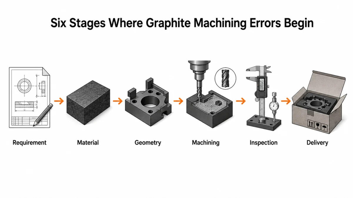
A root-cause review should move backward from the first confirmed defect, not forward from the most familiar explanation. The six stages provide a location map: requirement, material, geometry, machining, inspection, and delivery. A cause is credible only when it explains the defect pattern and is supported by evidence from the relevant stage.
| Stage | Failure that can enter here | Evidence that closes or reopens the stage |
|---|---|---|
| 1. Requirement | The application, functional surface, atmosphere, temperature, electrical or thermal duty, cleanliness, assembly condition, or delivery requirement is incomplete or misunderstood. | Approved requirement list, marked functional features, service boundary, acceptance method, and unresolved assumptions. |
| 2. Material | Wrong grade, lot, forming route, orientation, purity, coating, impregnation, blank condition, or undocumented substitution. | Supplier identity, exact grade and lot, data-sheet revision, orientation record, incoming condition, and approved equivalence decision. |
| 3. Geometry | Unsupported wall, exit edge, inaccessible hole, conflicting model and drawing, ambiguous datum, or undefined edge condition creates risk. | Controlled drawing and model, marked critical features, support and access review, edge policy, and agreed measurable acceptance. |
| 4. Machining | Tool wear, runout, path sequence, clamping, extraction, datum contamination, or uncontrolled process change creates the defect. | Program and setup revision, tool and fixture records, extraction status, first-good/first-bad comparison, and controlled confirmation run. |
| 5. Inspection | Dust, support state, contact force, instrument, temperature, sampling, or interpretation creates a false pass or false fail. | Measurement method, raw readings, calibration status, repeated result, support condition, and agreement on the decision rule. |
| 6. Delivery | Cleaning, handling, separation, restraint, stacking, moisture, impact, or unpacking damages a conforming part. | Condition photographs at each handoff, packing layout, receipt record, affected-position map, and verified packaging correction. |
Use the chain to challenge a proposed correction. If replacing the tool removes dimensional drift but transit chips remain, the tool change closed only one failure mode. If a finer grade reduces edge loss but the damage still appears at the same separator position, packaging remains open. Corrective action is complete only when the relevant stage evidence is updated and the result remains acceptable through delivery.
Application context may be reviewed through thermal management and high-temperature processing and the article on graphite parts for semiconductor-related equipment. Those pages help identify functional requirements; they do not determine the root cause of a specific defect without the project record.
Run a Controlled Root-Cause Review
A controlled review converts the complaint into a reproducible case. Freeze the current drawing, material identity, process revision, inspection method, and affected quantity. Identify the first confirmed-good and first confirmed-bad stage, rank the few causes that fit the pattern, and define one change with a measurable expected result.
- Containment: separate affected and unaffected parts, preserve representative evidence, stop unapproved rework, and identify what can still ship without mixing dispositions.
- Problem definition: state the observable defect, location, orientation, quantity, timing, and acceptance rule without embedding an assumed cause in the description.
- Hypothesis ranking: list only causes that explain the pattern and note what evidence would support or disprove each one.
- Controlled trial: change one primary variable where practical, keep material and geometry traceable, and inspect the first confirmation parts before continuing.
- Effectiveness check: verify the result through machining, cleaning, inspection, packing, and receipt when the original defect could enter after cutting.
- Record update: revise the drawing note, material control, setup, inspection method, cleaning instruction, or packing plan that allowed the failure to recur.
The graphite tolerance confirmation guide provides deeper datum and measurement questions. For drawing-based supply, the Custom Graphite Machined Parts and Graphite Block pages identify the product forms involved. A diagnosis should still be based on the actual defect evidence, not on the existence of a general capability page.
Conclusion
Graphite machining defects should be diagnosed from pattern, timing, and evidence. Chipping, drift, rough surfaces, thin-feature fractures, functional failures, and delivery damage can share the same visible symptom while originating at different stages.
The practical sequence is to preserve the part, identify the last confirmed-good stage, compare first-good and first-bad evidence, test the smallest credible cause set, and verify the correction through the stage where the defect originally appeared. This is more reliable than applying a generic machining rule to every failure.
For finished drawing-based components, review Custom Graphite Machined Parts. For raw material forms and grade discussions, review Graphite Block. These pages support inquiry preparation; the defect case still needs its own drawing, material, process, inspection, and handling evidence.
Frequently Asked Questions About Graphite Machining Defects
What evidence should be collected before a chipped edge is reworked?
Preserve photographs of the defect location and orientation, the first conforming and first failed parts, the exact grade and lot, tool and fixture history, the operation after which the chip first appears, cleaning records, and packing condition. Rework can remove fracture and contact marks, so containment and evidence collection should occur before blending or polishing.
How can machining drift be separated from measurement drift?
Plot raw values in production order, repeat the reading after controlled datum cleaning and support, record instrument and contact force, and compare another method where practical. Mark tool, offset, fixture, interruption, and inspection changes on the same trend. A correction is credible when the measured response follows the controlled change.
Does a rough graphite surface always mean the grade is too coarse?
No. Surface pattern can also reflect tool edge condition, runout, vibration, support, cutting direction, dust recutting, contamination, or cleaning damage. The named grade and particle metric are part of the evidence, but the pattern, location, process history, and functional requirement must agree before material is assigned as the cause.
Why can a thin wall break after it has already passed machining?
Support may be removed during unclamping, measurement force may be concentrated on the wall, cleaning may load the feature, or packaging may transfer impact or restraint into a weak section. Record the condition immediately after machining, after release, after cleaning, after inspection, and after packing to identify the first failed stage.
What does it mean when dimensions pass but the part still fails in use?
The drawing result may not cover material identity, orientation, surface integrity, cleanliness, pore condition, purity, coating readiness, electrical or thermal behavior, sealing performance, or installation damage. The investigation should return to the functional requirement and define evidence beyond dimensional conformity where the application requires it.
How should a corrective action be verified?
Define the expected result before the trial, change one primary variable where practical, inspect the first confirmation parts, and follow them through cleaning, inspection, packing, and receipt when those stages are relevant. Update the controlled record that allowed the failure, instead of relying only on a verbal process change.
What information should be sent to QDZRT Graphite for a defect review?
Send the current drawing and revision, exact material grade and lot if known, application, affected quantity, defect photographs with marked locations, first-good and first-bad sequence, tool and setup history, measurement method, cleaning route, and packing or arrival condition. Missing information should be identified as unknown rather than replaced with assumptions.
References & Sources
- NIST Dimensional Metrology — Uncertainty and Statistics — General measurement-uncertainty background; not proof of graphite-specific capability.
- NIST Dimensional Metrology — Measurement Assurance — General measurement-assurance and process-control background.
Send a Graphite Defect Case for Technical Review
For a root-cause review, start the inquiry through the contact page with the known material grade and lot, application, affected quantity, first-good and first-bad sequence, tool and setup history, measurement method, cleaning route, and packing or arrival condition. After we reply, send the latest controlled drawing, marked defect photographs, and other evidence by email or another agreed secure channel. QDZRT Graphite can review the supplied evidence and identify missing questions; final limits and corrective actions remain project-specific.