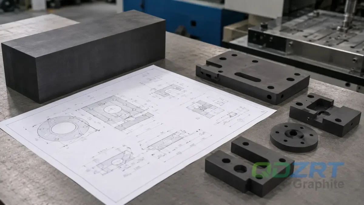
Thin walls and small holes change a custom graphite quotation because the feature—not the outside size alone—can control the manufacturing route. A 1.2 mm wall may need support until the final operation; a 1.5 mm hole with a depth of 12 mm creates an 8:1 depth-to-diameter condition; and a hole close to an outer edge may leave a fragile ligament. These features can affect grade selection, tool diameter, machining sequence, dust evacuation, inspection access, handling, expected yield, and packing.
QDZRT Graphite reviews fragile geometry feature by feature: when support disappears, where engagement or dust evacuation becomes concentrated, how the feature will be inspected, and whether it can survive cleaning, packing, transport, and assembly.
The numerical values in this article are DFM screening points, not fixed machining limits, acceptance criteria, guaranteed capabilities, or quotation commitments. Feasibility is decided from the controlling product definition, named graphite grade, blank orientation, geometry, tool access, tolerance, batch size, inspection method, service condition, and approved project plan.
1. Identify the Controlling Product Definition Before Quotation
A fragile-feature review starts by identifying the controlling product-definition source. Depending on the project, this may be an approved 2D drawing, an annotated 3D model, or a defined combination of both. A 3D model can be the formal product definition in a model-based definition project; it alone does not rank below a 2D drawing. The RFQ should state which file controls dimensions, tolerances, datums, notes, and acceptance requirements.
Before quotation, the review should confirm the file revision, approval status, units, datum structure, general tolerances, critical characteristics, and the rule to apply if the 2D and 3D data conflict. “Revision B or later” is not a sufficient instruction by itself: the relevant requirement is the specific approved revision. Millimetres are common for our team projects, but an inch-based definition is equally valid when clearly controlled.
This approach follows the principle in ASME Y14.41 digital product definition practices: product-definition authority, annotations, revision control, and dataset relationships must be clear. Our team uses that principle as an engineering communication framework; it does not supersede the customer drawing standard or contract requirements.
- Approved 2D drawing, annotated 3D model, or a defined combination of both
- Exact revision, units, scale policy, and customer approval status
- Datums and functional relationships that control assembly or service
- Critical dimensions that cannot be changed and dimensions open to DFM discussion
- Surface, edge, cleanliness, inspection, marking, and packing notes
- Conflict rule for differences among the drawing, model, purchase order, and later emails
Separate size tolerances from geometric controls. Hole diameter, wall thickness, flatness, parallelism, position, and runout answer different functional questions; a part can meet every local size dimension and still fail assembly because datum relationships or feature position are uncontrolled. Tight general tolerances can also add inspection and handling without improving function, so identify the functional surfaces and relationships instead of treating every printed decimal place as equally critical.
2. Preliminary DFM Review Triggers for Fragile Features
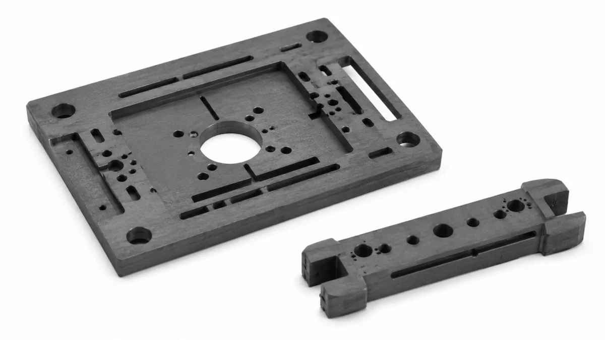
The first table flags geometry that deserves closer discussion before price, lead time, inspection, and expected yield are fixed. Crossing a trigger does not make a feature impossible or safe by itself; wall height, surrounding support, material structure, tolerance, and access still change the risk.
| Feature | Initial review trigger | Higher-risk interaction | Typical review effect |
|---|---|---|---|
| Unsupported wall | Thickness below 2.0 mm | Height above 4 times thickness | Staged roughing, temporary support, handling and inspection review. |
| Web between pockets | Web below 2.5 mm | Pocket depth above 20 mm | Balanced removal, remaining-web verification, and possible sequence change. |
| Small through-hole | Diameter below 2.0 mm | Edge distance below 1.5 times diameter | Entry support, exit breakout, remaining ligament, runout, and inspection review. |
| Deep blind hole | Depth above 6 times diameter | Diameter below 3.0 mm | Tool reach, dust evacuation, bottom geometry, and depth-method review. |
| Narrow groove | Width below 2.0 mm | Depth above 5 times width | Small-tool stiffness, dust path, bottom radius, and inspection-access review. |
| Sharp inside corner | Radius below 0.5 mm | Adjacent wall below 3.0 mm | Tool-radius, functional need, and local section-strength review. |
| Slender pin or boss | Diameter below 3.0 mm | Height above 5 times diameter | Late-stage finishing, low-force inspection, and protected handling. |
| Broad thin plate | Thickness below 5.0 mm | Span above 150 mm | Support, flatness, roughing symmetry, and packing review. |
Definition used in this article: Unless the controlling drawing states otherwise, hole edge distance means the shortest distance from the finished hole edge to the nearest finished outer edge—not the distance from the hole centre. Ratios and dimensions are project review triggers only.
3. Fragile-Feature Control Chain
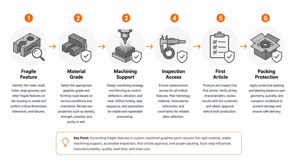
A fragile feature should survive more than the cutting operation. The proposed control chain for this article is: Fragile Feature → Material Grade → Machining Support → Inspection Access → First Article → Packing Protection. Each handoff asks a different question: what the feature must do, what material supports it, how it remains supported during machining, how it will be measured, what first-article evidence is required, and how contact or vibration will be prevented in shipment.
The chain is a visual overview and navigation aid, not a second set of limits. Inspection reports, special fixtures, prototype quantities, and packing designs remain project deliverables that must be defined in the quotation or approved quality plan.
4. Use a Feature Survival Map Where the Project Risk Justifies It
For drawing-based projects reviewed and accepted by our team, a five-stage feature survival map can be used as a project review framework. It is most useful when several fragile conditions interact, when inspection access is uncertain, or when a sample route must be converted into repeat production. It is not an automatic deliverable for every preliminary inquiry.
| Exposure stage | Thin-wall risk | Small-hole risk | Project control question |
|---|---|---|---|
| 1. Blank preparation | Saw breakout within 3–5 mm of the future wall zone | Contamination or surface damage at the planned entry face | Leave suitable allowance and orient the blank with the approved grade and direction. |
| 2. Roughing | Unequal stock removal across a span above 100 mm may reduce support | Pocket dust can be recut near a later hole location | Balance removal and retain local support where practical. |
| 3. Finishing | A wall below 2 mm may have limited radial stiffness | A hole below 2 mm can become sensitive to runout and breakout | Use the approved tool path, controlled engagement, and an exit strategy suited to the feature. |
| 4. Inspection | Probe, clamp, or fixture force can deflect or chip the wall | Gauge entry can damage a small bore edge | Define support, contact force, access, and measurement method before approval. |
| 5. Shipment | Vibration or foam preload can contact a rim or wall | Loose particles can lodge in a small bore | Use clearance, rigid support, clean bagging where required, and movement restraint. |
The map prevents a narrow interpretation of feasibility. “The machine can reach it” is only one condition. The feature must also be inspectable, cleanable, identifiable, and transportable. Related interactions are discussed in graphite machining challenges and the five keys to successful graphite machining.
5. Review Thin Walls Together With the Named Material Grade
Thin walls occur in graphite trays, rings, holders, plates, fixtures, furnace components, and sealing-related parts. A thin wall is not only a nominal dimension. Its behaviour depends on height, free span, interruptions, adjacent holes, load direction, tool access, workholding, blank orientation, and the graphite grade. A short supported wall may be practical below a preliminary trigger, while a taller interrupted wall can remain risky above the same nominal thickness.
Material descriptions must also separate different dimensions. “Graphite block” describes a supply form. Isostatic pressing, extrusion, vibration molding, and die molding describe forming routes. Fine grain describes microstructure, while high purity describes a purity condition. None of these labels alone proves a geometry capability. Our team reviews the named grade or an approved property range, including forming route, orientation, grain size, density, flexural and compressive strength where relevant, porosity, purity or ash, and the intended service condition.
The forming method matters because industrial graphite grades can differ in directionality, strength, pore structure, and machining response. SGL Carbon’s graphite overview describes multiple forming routes and the resulting material differences. The article uses this source to support material-selection principles, not to claim that a named supplier grade is equivalent to one of our grades or to guarantee a specific wall thickness.
Blank orientation can be especially important for a long wall, ring rim, or loaded boss. A direction that is convenient for stock yield may not be the best direction for strength, dimensional stability, thermal flow, or repeated handling. When directionality matters, the approved drawing or material note should identify the required orientation and the supplier should preserve that relationship through blank cutting and traceability. Where the grade is treated as near-isotropic, that assumption should still be based on the named grade data rather than the word “isostatic” alone.
| Wall condition | Project example | Primary concern | Possible design or process response |
|---|---|---|---|
| Short supported wall | 2.0–3.0 mm thick; height below 3 times thickness | Local edge chipping | Small edge radius, protected finishing pass, and defined handling points. |
| Tall unsupported wall | Below 2.5 mm; height above 4 times thickness | Deflection or fracture during contouring | Retain sacrificial support, finish late, change sequence, or review thickness. |
| Wide thin plate | Below 5.0 mm; free span above 150 mm | Flatness and handling distortion | Balanced roughing, full-face support, measurement method, and rigid pack. |
| Pocket web | Below 2.5 mm between cavities | Breakthrough or local cracking | Machine pockets in a balanced sequence and verify remaining web. |
| Interrupted wall | Opening removes more than 40% of wall length | Stress concentration near opening corners | Add radius, increase local section, or change the operation order. |
| Ring rim | Radial wall below 2.0 mm; diameter above 100 mm | Chipping under workholding or transport contact | Use an approved full-support concept and non-contact packing clearance. |
| Threaded thin section | Thread edge distance below 2 times major diameter | Cracking under assembly torque | Review boss size, insert concept, engagement, and assembly torque. |
| Thermally cycled wall | Temperature change above 500 °C in service | Sensitivity to gradients, oxidation, and restraints | Review grade, atmosphere, section transitions, assembly freedom, and service validation. |
The thermal example above is a service-risk trigger, not a machining limit. A 500 °C change does not by itself define graphite suitability. Atmosphere, heating rate, constraint, oxidation, grade, geometry, and cycle life must also be considered. This distinction separates machining risk from service risk.
6. Small Holes, Deep Grooves, Threads, and Sharp Edges Need Separate Questions
A shallow hole in an open surface is different from a deep blind hole, a cross hole, or a hole near a thin edge. The review should distinguish through and blind conditions, entry and exit faces, hole-to-edge and hole-to-hole ligaments, bottom form, tool reach, dust path, positional relationship, and inspection access. The same principle applies to narrow grooves and small threaded holes.
Sharp inside corners are often copied from metal drawings. In graphite, the functional requirement should be separated from the graphical appearance. A small cutter may create a small radius, but the result can add tool time, inspection difficulty, and local fragility. Outside edges may survive machining and still be damaged during cleaning, inspection, packing, or assembly. Before sampling, the drawing should identify which edges are functional, which are cosmetic, and which can accept a radius or chamfer.
| Feature condition | Project example | Machining question | Inspection question |
|---|---|---|---|
| Through-hole in thin plate | Diameter 1.0–2.0 mm; plate 2–5 mm | How will entry support and exit breakout be controlled? | Will a pin, optical method, or agreed go/no-go check be used? |
| Deep blind hole | Depth 6–10 times diameter | Can dust leave without repeated recutting or tool binding? | How are diameter, depth, taper, and bottom form assessed? |
| Cross hole | Intersection within 2 diameters of outer wall | Will the second hole break into a weakened ligament? | How is the intersection inspected without damaging the edge? |
| Hole near outer edge | Finished edge distance below 1.5 times diameter | Which cutting direction and support protect the remaining ligament? | Is edge chipping a separately defined acceptance characteristic? |
| Hole pattern | Pitch below 2.5 times diameter | Does the pattern leave enough web between holes? | Are position, diameter, and remaining web all function-critical? |
| Narrow deep slot | Width 1–2 mm; depth above 5 times width | Is the tool sufficiently stiff and can dust escape? | How are width, depth, radius, and blockage checked? |
| Bottomed counterbore | Step below 1 mm; diameter ratio above 2:1 | Can the shoulder be produced without overcut or packed dust? | Which datum defines depth and shoulder location? |
| Small threaded hole | Below M6; engagement above 2 diameters | Is a direct graphite thread suitable for the assembly load? | Which gauge, fit, and torque condition define acceptance? |
These examples are not a universal minimum-hole chart. A feature may be feasible outside the stated bands when the grade, aspect ratio, support, tolerance, tool, quantity, and inspection method are suitable. Conversely, a nominally larger feature may remain unsuitable when it intersects a fragile wall or cannot be inspected without damage.
7. Inspection Access and First-Article Evidence Must Be Defined Before Release
A feature is not fully defined until the acceptance method is known. Small bores may require pins, optical measurement, air gauging, sectioning, or an agreed functional check. Thin walls may require low-force support, limited contact points, or a non-contact method. The selected method should address measurement range, access, contact force, datum setup, uncertainty, temperature, repeatability, and risk of damaging the feature.
NIST’s metrological traceability guidance supports the need to understand the measurement result, the calibration chain, and measurement uncertainty. It does not prescribe a 2 mm wall, a 6:1 hole ratio, a graphite machining capability, or a fixed sampling frequency. NIST also cautions that traceability alone does not prove that a measurement is suitable for its intended use.
The original micro-feature references remain useful for general context: NIST’s micro-hole shadow-measurement article, NIST dimensional metrology for micro and mesoscale manufacturing, and the OSTI mesoscale machining report. They do not establish production limits for our team.
Where uncertainty remains, an agreed first article can create project evidence. The report scope may include hole size, depth, wall condition, edge condition, flatness, surface appearance, cleanliness, and packing condition against the approved revision. A first article is not required for every order by default; the quantity, measurement extent, report format, and customer hold point must be stated in the quotation or quality plan.
The specification limit and any process-control limit must also remain separate. A drawing tolerance defines the acceptable product result; an internal process-control band is a manufacturing tool used to react before the specification is exceeded. Without an approved statistical method, a trend toward a “control limit” does not by itself trigger a universal inspection rule. For a small batch, the practical plan may instead use defined first, middle, and last pieces, 100% checks of one critical feature, or a customer-approved functional gauge.
8. Make Quotation Assumptions Visible Without Pretending to Disclose Every Internal Cost
Fragile features can change material allowance, programming, workholding, machining sequence, inspection, handling, expected yield, sample quantity, and packing. A useful quotation makes the assumptions and major cost drivers visible where they materially affect feasibility, lead time, inspection, or delivery. It does not need to disclose every internal labour or overhead calculation as a separate line item.
Illustrative scenarios such as one prototype followed by 50 production pieces can be retained for planning, but they are not a fixed our quotation structure. The appropriate route depends on part value, feature interaction, material availability, tooling, customer approval requirements, repeatability evidence, and the risk of changing the process after the first article.
Related commercial and technical review topics appear in the custom graphite manufacturer guide, the precision graphite machining guide, and OEM customization options. Export packing considerations are discussed in graphite packaging and logistics planning.
9. Keep Technical Release, Export-Control Review, and Shipment Release Separate
A machining result, an export-control decision, and a shipment release are three different decisions. A part can be technically feasible but not yet approved for export. A first article can pass dimensional inspection while end-user, end-use, destination, classification, or licence questions remain open. A packed part should not be released merely because the packaging is complete.
For export projects, our team collects technical and commercial information and coordinates documentation within the agreed scope. The exporter remains responsible for product identification, licence application where required, and truthful declaration; the competent authority decides licensing, and customs supervises declaration and release. The exact graphite material, form, technical parameters, destination, end user, and end use must be reviewed under the rules applicable at the time of shipment. The 2026 dual-use item licence-management notice is included as a current official reference, not as a conclusion that every machined graphite part is controlled.
Three separate gates: Technical Release confirms the approved drawing and manufacturing evidence. Export-Control Review confirms the compliance path and required documents. Shipment Release confirms quantity, identification, packaging, documents, and authorization to dispatch.
Dust control is also separate from product cleanliness. The OSHA synthetic graphite page provides U.S. occupational-health context. Actual controls depend on the material, SDS, local law, equipment, extraction, housekeeping, and site risk assessment; OSHA values should not be presented as universal global limits or as product-cleanliness specifications.
Packing release should refer back to the fragile-feature map. Foam or a bag should not press directly on a thin rim, a narrow boss, or a sharp functional edge. Small bores may need cleanliness confirmation before bagging, while broad thin plates may need full-face support and a rigid board or crate that prevents bending. The approved pack can include orientation marks, part separation, movement restraint, moisture protection where appropriate, and a packing-list link to the drawing revision. These controls protect the accepted part; they do not substitute for the separate export-control review.
10. What to Send Before Asking for a Quote
A clear RFQ does not need to be long, but it should allow material, geometry, inspection, quantity, and delivery to be reviewed together. When information is not final, identify the open point instead of leaving an assumption unrecorded.
- Controlling 2D drawing, annotated 3D model, or defined combination, with exact revision and units
- Application, working atmosphere, temperature range, load, contact media, and expected service cycle where relevant
- Named graphite grade or approved property range; current grade if the part is a replacement
- Critical dimensions, datum relationships, functional edges, and dimensions open to DFM adjustment
- Hole sections, blind-hole bottoms, cross holes, groove radii, and thread details that are not clear in the main view
- Prototype quantity, expected repeat quantity, inspection output, customer hold points, and acceptance method
- Cleaning, marking, traceability, coating, impregnation, purification, or special surface-condition requirements
- Destination country, transport route, packing constraints, and any known compliance or end-use documentation needs
The graphite block material range can support an initial material discussion, while graphite block specification mistakes explains why density alone is not enough. For EDM projects, see EDM graphite electrode machining basics, the EDM tooling solution, and the graphite block selection guide for EDM electrodes. For clean or semiconductor-related applications, use the semiconductor-related graphite parts review.
11. Project-Scope Boundary
For drawing-based projects reviewed and accepted by our team, the review can connect the product definition, named material basis, fragile-feature DFM, inspection evidence, packing plan, and export-documentation path. The exact deliverables depend on the quotation. A preliminary RFQ review does not include by default a full risk map, special fixture design, full-dimensional first-article report, 100% inspection, material laboratory testing, special cleaning, coating, revalidation, or custom export pack.
This project boundary protects both parties. The customer can see which evidence and services are included, while our team avoids turning an early engineering discussion into an unintended universal guarantee. The company profile describes the business scope of our team, and the contact page provides the route to start the inquiry. After we reply, controlled drawings, CAD files, and other project documents should be exchanged by email or another agreed secure channel.
The shop-floor comparison of graphite and metal cutting explains why metal-style coolant and tooling assumptions do not transfer directly. Material, process, and evidence should be aligned before price or lead time is treated as final.
Frequently Asked Questions
Why can a thin wall increase cost even when little material is removed?
The wall can control the operation sequence, support strategy, tool engagement, inspection method, handling, expected yield, and packing clearance. Surrounding stock may need to remain until late in the cycle, and the approved route may require a first-article hold point.
Is 2 mm a fixed minimum wall thickness for every graphite part?
No. Two millimetres is a preliminary review trigger used in this article. A shorter supported wall may be practical below it, while a taller, interrupted, thermally loaded, or difficult-to-inspect wall can remain risky above it.
What makes a small blind hole different from a through-hole?
A blind hole adds depth control, bottom-form requirements, trapped dust, reduced tool stiffness, and less direct inspection access. A through-hole adds exit breakout and support questions. Neither condition is automatically easier without the full geometry and acceptance method.
Can a sharp inside corner be produced in graphite?
It depends on the required radius, depth, tool access, adjacent section, grade, tolerance, and function. Our team separates a functional corner requirement from a cosmetic preference before proposing a tool and inspection route.
When is a prototype useful for fragile graphite geometry?
A prototype is useful when several review triggers interact, when the measurement method is not yet proven, when the design was transferred from another material, or when customer approval is required before repeat production. The need and report scope must be agreed.
How should graphite edge chips be evaluated?
Functional and cosmetic edges should be identified separately. Acceptance may use a written size limit, a visual standard, a protected-zone rule, or a customer-approved first article. The same classification should continue through cleaning and packing.
What information improves a small-hole quotation?
Provide diameter, depth, through or blind condition, bottom form, position tolerance, finished edge distance, intersecting features, grade or service condition, quantity, and the intended inspection method. A section view is often more useful than a single top view.
References and Sources
- ASME Y14.41 — Digital Product Definition Data Practices: product-definition and model-based dataset principles.
- NIST — Metrological Traceability: calibration-chain, uncertainty, and fitness-for-purpose boundaries.
- NIST — Shadow Technique Improves Measurement of Micro Holes: general micro-hole measurement context.
- NIST — Dimensional Metrology for Micro and Mesoscale Manufacturing: access and micro-feature metrology context.
- OSTI — Meso-scale Machining Capabilities and Issues: general small-feature machining context, not our team capability evidence.
- MOFCOM — 2026 dual-use item licence-management notice: current official compliance reference.
Drawing Review for Thin Walls and Small Holes
QDZRT Graphite reviews fragile geometry before a sample or production quotation is released. Send the approved product definition, application, named material basis, quantity path, critical tolerances, inspection output, and delivery route through the contact page. The review will identify which assumptions can be quoted, which features need clarification, and which evidence or compliance steps need agreement before production or shipment.