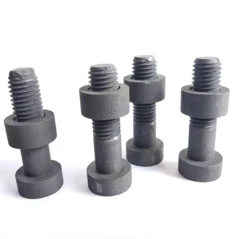
Before ordering a custom graphite part, the drawing is only half of the information the supplier needs. A graphite part can match the drawing and still fail in use. The usual reason is not the CNC program alone. It is often the graphite grade, thin-wall design, sharp edge, tolerance plan, surface requirement, or working environment that was not confirmed before machining.
That is why precision graphite machining should be reviewed as an application problem, not only a size problem. QDZRT Graphite supplies drawing-based custom graphite machined parts for EDM, thermal processing, metallurgy, sealing systems, semiconductor-related equipment, furnace fixtures, and other industrial assemblies. For these parts, the key question is: Will this material, geometry, and tolerance still make sense after the part is installed and used?
Application-first review: Graphite machining should start with the working condition, not only the drawing size. The same drawing may require a different grade, tolerance plan, edge policy, cleaning route, or packing method depending on temperature, load, atmosphere, electrical function, sealing duty, or cleanliness requirements.
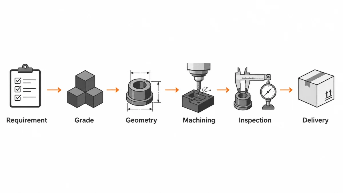
1. Review the Drawing and the Application Together
A drawing gives the supplier the shape, dimensions, holes, slots, and tolerances. That is necessary, but it is not always enough for graphite. Graphite is brittle compared with metal, and different grades behave differently during machining and service.
A good graphite machining review checks the drawing and the application together. If the part is used as an EDM electrode, a furnace support, a sealing ring, or a positioning fixture, the same dimension may carry a different functional meaning.
Drawing risk: A metal-style drawing may define size correctly but omit the graphite-specific function of a contact face, mounting relationship, protected edge, or minimum stable wall. Our team therefore reviews the drawing against the application before material release.
Useful RFQ content: material selection or request for grade recommendation; application; marked functional faces; small holes, thin ribs, sealing edges, or locating steps; and whether the quantity is a prototype, trial lot, or production batch.
Suggested drawing note: “Please review the drawing for graphite-machining feasibility. The marked faces are functional. Our team may recommend the grade after reviewing working temperature, atmosphere, load, cleanliness, and quantity.”
Our team converts the drawing into a feature map that gives each datum, fit, seal, contact face, hole pattern, edge, and fragile section a manufacturing and inspection purpose. Application data then explains which of those features carries function; a furnace support, EDM electrode, and semiconductor fixture can share nominal dimensions yet require different material, cleaning, and edge policies.
The graphite drawing-review guide covers geometry-specific risks, while the tolerance confirmation guide explains revision, datum, and measurement control.
2. Define the Graphite Grade by Forming Route and Properties
Our team machines a range of synthetic graphite grades, including isostatically pressed, extruded, vibration-molded, and die-molded materials, subject to grade availability, drawing review, and application requirements. The selected grade is further defined by grain structure, pore distribution, strength, hardness, purity, anisotropy, and intended service conditions.
Material selection affects machinability, edge quality, strength, purity, thermal behavior, and dimensional stability. A graphite block that is suitable for a furnace support may not be suitable for a fine EDM electrode. A grade that machines well for a large plate may not be ideal for thin ribs or small holes.
| Application Type | What Usually Matters | What to Confirm Before Machining |
|---|---|---|
| EDM electrodes and mold inserts | Fine detail, stable machining behavior, repeatable geometry | Grain structure, feature size, corner detail, electrode quantity |
| Furnace fixtures and thermal parts | Thermal stability, atmosphere, load, part support | Working temperature, atmosphere, contact points, wall thickness |
| Sealing rings and bushings | Contact surface, wear behavior, dimensional fit | Functional faces, mating part, friction condition, surface requirement |
| Semiconductor-related parts | Cleanliness, stability, contamination sensitivity | Purity expectation, handling requirement, packaging condition |
| Metallurgy and casting tooling | Heat resistance, thermal cycling, shape durability | Temperature range, metal contact, replacement frequency, geometry risk |
Note: Material choice needs confirmation by geometry, application temperature, atmosphere, load, and cleanliness requirements.
Machine accuracy is only one part of precision. Particle size, pore distribution, strength, hardness, forming method, and anisotropy affect edge stability and dimensional repeatability, so the project should use a named grade or approved property envelope and link the batch to the part report rather than substitute on density alone.
Manufacturer data illustrates why these attributes must be kept separate. SGL Carbon describes isostatic pressing, extrusion, vibration molding, and die molding as forming routes, while its isostatic grades are additionally characterized by fine grain structure, isotropy, and optional high-purity treatment. Entegris POCO classifies graphite grades by application and grain size, and Toyo Tanso separately identifies isotropic structure, purity, and coating technology. These examples support grade-by-grade review instead of substitution by one density value or one broad material label.
For stock material, see Graphite Block and the graphite block mistakes guide. EDM-specific grade selection is covered in choosing graphite for EDM electrodes.
3. Apply Functional Tolerances
Tight tolerances are sometimes necessary. They can also create unnecessary cost when they are applied to every face, slot, and non-contact edge. In graphite machining, tolerance decisions should follow function.
A practical tolerance plan separates functional dimensions from general dimensions. A sealing face, locating diameter, electrode detail, or assembly step may need close control. A clearance edge or non-contact surface may not.
Applicability boundary: The numerical values below are practical our DFM and first-article review starting points, not fixed graphite-machining capability or acceptance limits. Final tolerances, geometry limits, pilot quantity, inspection frequency, and measurement method depend on the named grade, feature geometry, drawing revision, order quantity, process evidence, and approved inspection plan.
Practical DFM Review Starting Points
| Control point | Illustrative numerical trigger | Precision implication |
|---|---|---|
| General vs critical tolerance | General ±0.10 mm; controlled ±0.05 mm; critical review at ±0.025 mm or tighter | These are review bands, not universal capability. Datum, geometry, grade, tool, and measurement decide feasibility. |
| Small hole | Diameter below 2 mm or depth above 6× diameter | Review tool reach, dust evacuation, exit support, and gauge access. |
| Thin wall | Below 2 mm or height above 4× thickness | Review support, roughing sequence, measurement force, and packing. |
| Inspection cadence | First-off 100% of critical features; stable lot example every 10 pieces | Actual sampling follows risk and evidence; the plan is stated before production. |
| Measurement uncertainty | Target measurement capability preferably below about 20–30% of tolerance width | Use an instrument and method capable of distinguishing process variation from measurement variation. |
Precision definition: A precise graphite part is not merely one that produces a close number on one instrument. The material, datum, process, measurement method, and delivery condition must reproduce the same functional result across the lot.
Cost consequence: Selecting a grade only by price can increase total cost through chipped edges, unstable fit, short service life or repeated machining changes.
Weak drawing note: “All dimensions ±0.02 mm.” This does not distinguish function, datum, or inspection method.
Better drawing note: “Marked locating faces and hole positions are critical. Other non-functional dimensions may follow the general machining tolerance agreed after our team reviews the drawing.”
Tolerance risk: Applying a tight tolerance to non-functional graphite surfaces increases machining, inspection, and scrap exposure without necessarily improving service performance.
A tolerance is assigned to a function and a method. Our team separates assembly diameters, sealing faces, locating holes, electrical-contact geometry, and reference dimensions. Critical features receive defined datums and sampling; general surfaces use a practical value. This reduces unnecessary finishing and avoids measuring fragile graphite with excessive contact force.
NIST guidance supports measurement uncertainty, calibration traceability and method control. The graphite-specific thresholds used here—such as ±0.10 mm, ±0.05 mm, ±0.025 mm, 2 mm, a 6× depth-to-diameter review point, 3–5 piece pilots and interval sampling—are screening starting points for project review and must be checked against the actual feature and inspection plan. NIST measurement traceability guidance notes that traceability alone does not establish whether a measurement result is fit for its intended decision.
4. Review Geometry Risks Before Cutting
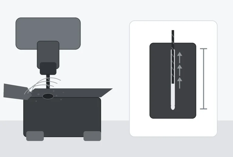
Graphite is machinable, but it is not forgiving in every shape. Thin walls can vibrate or break. Sharp external corners can chip during machining, cleaning, packing, or installation. Deep holes and narrow slots may require special tool access and dust control.
Geometry risk should be discussed openly before production instead of being discovered after the first part breaks. This is especially important for small precision parts, EDM electrodes, furnace fixtures with long unsupported sections, and graphite parts with sealing edges.
1Thin walls: review unsupported sections before machining.
2Sharp corners: confirm whether the edge is functional or only cosmetic.
3Deep holes and narrow slots: check tool access, dust removal, and edge condition.
Design reminder: A feature that is easy to cut in aluminum may be fragile in graphite. When a sharp edge is not functional, a small chamfer or radius is usually more stable than a knife edge.
Edge policy: Non-functional sharp edges may use an agreed small chamfer. Functional sealing or contact edges require a defined allowable edge condition and protection through machining, cleaning, inspection, and packing.
Fragile features combine machining and inspection risk: a deep hole can trap dust and block reliable probing, a thin wall can move under fixture or gauge force, and a sharp edge can be lost after inspection during packing. Review support, sequence, tool access, cleaning, inspection access, and final restraint as one route.
The thin-wall and small-hole guide explains how these features affect process time and risk. The graphite machining challenges article covers workholding and dust.
5. Control Machining, Dust, Handling, and Cleanliness
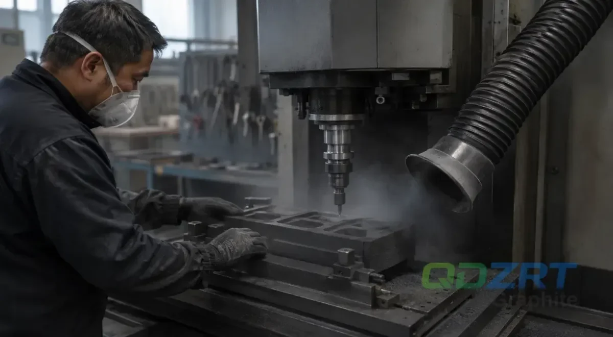
Graphite machining produces fine dust. That dust is not just a cleaning issue. It can affect machine maintenance, surface finish, measurement accuracy, and the cleanliness of finished parts.
For precision graphite parts, machining, cleaning, inspection, and packaging belong to the same process. A part can be machined correctly and still be damaged later if thin edges are not protected, if dust remains in small holes, or if functional faces are rubbed during packing.
Dust and handling risk: Graphite dust can affect surface condition, measurement stability, equipment maintenance, and finished-part cleanliness; fragile features can also be damaged after machining if handling and packing are not managed.
Inspection points to confirm:
- Critical dimensions and marked functional faces
- Flatness or parallelism if required by assembly
- Edge condition on sealing, locating, or contact areas
- Hole cleanliness and slot condition
- Packaging protection for thin or precision features
The accepted dimension must be measured on a clean, stable surface and remain protected afterward. Local extraction, clean supports, staged cleaning, managed contact and separated packing help protect both measurement and finished surfaces. The cited NIOSH and OSHA material provides United States occupational-hygiene context for synthetic graphite dust; the facility program still follows the material identity, SDS, local law, exposure assessment and site controls. Product cleanliness is a separate order requirement tied to the application.
For process context, see successful graphite machining and graphite packaging and logistics.
Precision Control Stack
The stack below assigns evidence to each control layer without treating one sampling interval or one measurement ratio as universal. Our team defines the final values in the approved project plan.
| Layer | Controlled item | Evidence |
|---|---|---|
| Layer 1 — Requirement — Current drawing revision and all agreed critical features | Application, drawing revision, critical features, and acceptance state | Approved technical review and marked drawing. |
| Layer 2 — Material — Approved grade, batch identity, and orientation rule where relevant | Exact grade, property basis, batch, and substitution boundary | Certificate, incoming identity, and approved substitution rule. |
| Layer 3 — Process — Approved first-off plus a risk-based interval | Fixture, roughing and finishing sequence, tool-life rule, extraction, and cleaning | Setup sheet, program revision, and first-off approval. |
| Layer 4 — Measurement — Feature-specific method with adequate resolution and uncertainty | Datum, instrument, force, environment, sampling, and report | Inspection plan and revision-controlled results. |
| Layer 5 — Delivery — Reconciled quantity, separation, support, labels, and package count | Part separation, edge protection, cleanliness, labels, and package reconciliation | Packing specification and release checklist. |
6. Inspection Access and Measurement Control
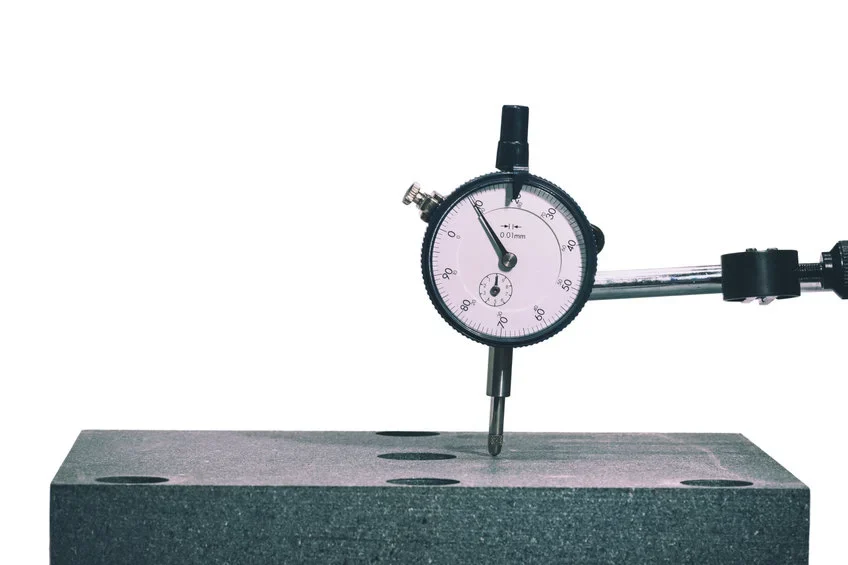
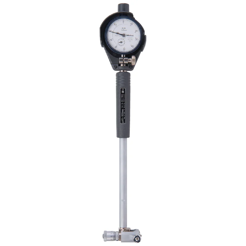
The thresholds in this access map flag features for early DFM and metrology attention; they are not automatic rejection limits or guaranteed capability. The named grade, span, wall support, datum, probe access, contact force, instrument, and acceptance method remain decisive.
| Feature | Preferred method | Access risk | Design response |
|---|---|---|---|
| Broad flat face; review flatness below 0.05 mm or span above 200 mm | Surface plate/height method or CMM where appropriate | Dust or local pore contact can affect reading | Define datum cleaning and contact locations. |
| Small bore; diameter below 2 mm or depth above 6× diameter | Pin/plug gauge, optical or CMM method as suitable | Gauge force and depth access | Define gauge class, depth, and entry/exit condition. |
| Thin wall thickness; below 2 mm or height above 4× thickness | Low-force micrometer, optical, or CMM method | Compression or edge damage | Use controlled force and protected measurement zones. |
| Hole position; positional tolerance below 0.05 mm or edge distance below 1.5× diameter | CMM/optical coordinate method from defined datums | Datum instability and probe access | Provide stable datum faces and probe clearance. |
| Sharp edge/rib; edge break below 0.2 mm or rib width below 1.5 mm | Optical inspection and dimensional method | Contact can destroy the feature | Define magnification and maximum edge break. |
The OEM customization guide and manufacturer evaluation guide explain how these controls enter quotation and repeat production.
7. First-Article Verification
For a precision graphite part, the first article tests the complete control stack, not only the CNC program. Our team begins with one active drawing revision and one approved material identity. The setup record identifies support and clamping locations, tool IDs, roughing and finishing sequence, extraction condition, cleaning method, datum preparation, and the planned instrument for each critical feature. The first part is then measured in the same free or restrained state defined by the drawing review.
The study separates machine correction from material or measurement effects. When an outside diameter is high, the part is first cleaned and remeasured using the defined locations and contact force. If the reading changes, dust, support, temperature, or instrument alignment may be involved. If the reading is stable but an edge condition has worsened, tool wear or cutting sequence is investigated before a blind program offset is applied. This avoids compensating the wrong cause and creating a new error elsewhere.
The following gates are practical first-article controls. A 3–5 piece pilot, 100% first-off inspection, repeat measurement, and interval checks are examples for project planning; the approved drawing, quantity, risk, material behavior, and customer requirements set the final plan.
- Identity gate: confirm one grade, batch, part number, drawing revision, and unit system before cutting.
- First-off gate: inspect 100% of critical dimensions, form controls, small holes, and protected edges on the first part.
- Repeatability gate: repeat at least one critical feature after cleaning, unclamping, and re-fixturing to reveal measurement-state effects.
- Pilot gate: an illustrative 3–5 piece pilot establishes dimensional and edge trends before a longer lot is released.
- Tool-life gate: compare first-off results with an interval such as every 5–10 pieces, then adjust the interval from actual trend evidence.
- Delivery gate: verify that packing supports the accepted datums and prevents contact with edges below the agreed chamfer or chip limit.
Capability is not represented by one best part. It is the demonstrated ability to keep the required feature distribution inside the acceptance limits with a measurement method that can resolve the change. Where a formal statistical capability index is requested, the sample size, distribution assumptions, measurement uncertainty, and material-lot effects must be agreed; a short pilot should not be presented as long-term capability without qualification.
The study output becomes the baseline for repeat orders: drawing revision, grade and batch rule, setup, tool-life limit, inspection method, sampling, cleaning, and packing. Any later change to grade, machine, fixture, tool, purification, coating, inspection, or packaging is compared with that baseline before existing approval is reused.
8. RFQ and Repeat-Order Control
A clear RFQ allows our team to quote the material, machining route, inspection scope, cleaning, and packing against one current requirement set. It also identifies open technical points before material release.
For custom graphite machined parts, send the drawing together with the working condition. When the grade is not fixed, our team reviews the application and proposes a material selection subject to grade availability, geometry, quantity, and final approval.
Useful RFQ sentence: “Please review the drawing and identify features that may be difficult or fragile in graphite before production.”
Recommended RFQ information:
- Drawing, sample, sketch, or target dimensions
- Required graphite grade, or application details if the grade is unknown
- Quantity: prototype, trial order, or batch supply
- Tolerance, surface, flatness, parallelism, and edge requirements
- Working temperature, atmosphere, load, wear condition, or electrical/thermal function
- Whether the part is for EDM, furnace, metallurgy, sealing, semiconductor-related equipment, or another industrial assembly
- Packaging, inspection, and delivery requirements for finished parts
The quotation package should contain one current drawing revision, a 3D reference file where useful, exact grade or application, quantity, critical features, edge policy, cleanliness, inspection, and packing. Our team records open points before material release. Finished components follow the Custom Graphite Machined Parts route.
Relevant application pages include EDM and precision tooling, high-temperature processing, and semiconductor-related graphite parts.
Practical Conclusion
Precision graphite machining is most reliable when our team reviews why the part is being made, not only its nominal dimensions. A current drawing, approved grade, functional tolerance plan, geometry review, clean measurement method, first-article evidence, and protected delivery state prevent many failures before production expands.
Final review rule: For thin walls, small holes, sealing faces, EDM details, high-temperature service, or contamination-sensitive use, send the drawing with the application notes so our team can review grade, feasibility, inspection, cleaning, and packing before cutting begins.
For material and machining options, review our Custom Graphite Machined Parts page. For electrode and tooling applications, the EDM and Precision Tooling page is more relevant.
Frequently Asked Questions
What is precision graphite machining?
Precision graphite machining means producing features whose material, geometry, datum, process, measurement, and delivery state are defined together. A single close measurement is not enough. A reliable route needs repeatable grade identity, first-off evidence, tool and setup control, feature-specific inspection, and packing that preserves the accepted condition.
How tight can graphite tolerances be?
There is no single value that fits every part. Broad supported features can usually be controlled more easily than thin walls, deep holes, or fragile edges. The practical tolerance depends on grade, size, datum, tool access, environment, measurement capability, and quantity. Our team reviews the exact feature and method before accepting a tight value.
Does fine-grain graphite guarantee better precision?
Fine and uniform structure can support detail and edge stability, but strength, pore distribution, hardness, forming method, and tool behavior also matter. The finest grade may add cost without benefit on a large simple part. Our team matches the full material data to the smallest functional feature and service condition.
Why is measurement force important?
Graphite surfaces and thin sections can be damaged or locally influenced by concentrated contact. Excessive force can create false readings or chips. The instrument and contact method are selected for the feature, and datum surfaces are cleaned before measurement. Optical or coordinate methods may be preferred for fragile geometry.
How is dimensional drift detected?
Our team compares the approved first-off part with interval measurements on the features most sensitive to tool wear and setup change. A monotonic trend suggests tool or offset drift; random variation may indicate workholding, material, dust, or measurement problems. Corrective action follows the evidence instead of automatic offset changes.
What is included in a precision inspection report?
The report identifies part number, drawing revision, material/batch, quantity or sample, feature, nominal value, tolerance, measured result, units, method, and disposition. Additional photographs or surface observations can support the record. The exact scope follows the order and feature risk.
How are precision graphite parts packed?
Parts are separated so graphite surfaces and edges do not rub. Thin rings, ribs, and plates receive rigid support and carefully managed contact. Cleanliness-sensitive parts use agreed bagging or liners. Labels reconcile part number, revision, quantity, batch, and package count so the accepted condition remains traceable through shipment.
References & Sources
- NIST: Metrological Traceability — Supports calibration traceability and explains that traceability alone does not prove fitness for a specific measurement purpose.
Submit a Precision Graphite Part for Review
Start the inquiry through the QDZRT Graphite contact page with the grade or application, quantity, critical dimensions, datums, fragile features, inspection method, cleanliness, and packing. After we reply, send the latest controlled drawing by email or another agreed secure channel. The review defines the precision control stack before production.