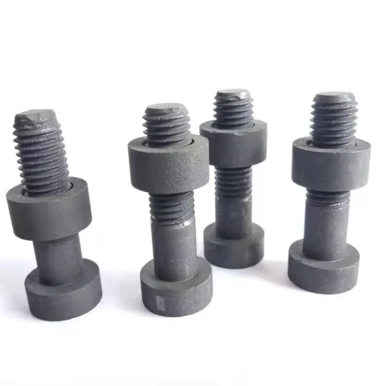
QDZRT Graphite manufactures graphite components to customer drawings. Our process review connects the specified grade, critical features, tooling and inspection requirements before production. The controls below explain how our team manages machining stability and what manufacturing information supports the finished part.
Our Machining-Process Review
| Parameter | Parameter-development requirement | What changes the range |
|---|---|---|
| Small-diameter end mill selected for the actual feature, grade, and tool-access condition | Build the rpm and chip-load range from a controlled first-off trial using the named grade, actual tool, engagement, extraction, and inspection plan. | Confirm actual tool diameter, flute count, named grade, radial engagement, axial depth, runout, rigidity, coating, and first-off result. |
| Larger end mill selected for the actual stock-removal and feature-support condition | For the larger cutter, start from machine limits and tool data, then verify the range against the named grade, engagement, extraction, and first-off result. | Confirm machine power, tool geometry, overhang, feature support, surface target, extraction, engagement, and first-off evidence. |
| Small-diameter drilling operation | Do not transfer a generic feed-per-revolution value. Develop the drilling cycle from diameter, depth, runout, backing support, extraction, and breakout risk. | Confirm depth, backing support, runout, named grade, peck strategy, extraction, and breakout requirement before the first-off trial. |
| Larger drilling operation | Generic feed-per-revolution values are not transferable here; set the drilling cycle from diameter, hole depth, tool material, wall proximity, extraction, and exit support. | Confirm diameter, hole depth, exit support, extraction, tool material, wall proximity, and first-off evidence before release. |
| U.S. occupational reference for synthetic graphite | OSHA PEL reference: 15 mg/m³ total and 5 mg/m³ respirable | Confirm material identity, SDS, local jurisdiction, exposure assessment, enclosure, extraction performance, maintenance, and work practice. |
Scope of the numbers: The table intentionally avoids publishing transferable cutting windows. It defines the evidence required before a parameter set can be approved for a specific part. Final parameters belong to the approved part revision and depend on the named grade, tool diameter, flute count, overhang, radial and axial engagement, geometry, machine rigidity, extraction, tool condition, and first-off result.
Graphite-Specific Program Validation
Our manufacturing review checks chip load, engagement, support, extraction, tool condition and edge risk against the specified graphite grade. These checks prevent a program developed for aluminum or steel from being released unchanged for a graphite component.
A machining program proven on metal does not transfer automatically to graphite.
The first warning usually appears at the edge. A corner chips. A fine rib breaks down. A pocket wall looks sandy instead of clean. Then the surface finish starts telling the same story: rough texture, microchipping, uneven machining marks, and tool wear that arrives much earlier than expected.
Graphite is not a softer version of metal. It removes by brittle microfracture and responds differently to tool edge condition, feed per tooth, engagement, workholding, and unsupported geometry. A metal-style program can move correctly while still producing chipped edges, unstable dimensions, or a damaged finish.
We define the machining route from the grade, drawing, tool geometry, engagement, extraction, surface requirement and first-article result. Our process record links the material batch, tool, setup, feature risks, inspection method and delivery condition.
The failure is usually not “too fast” in isolation. It is an incompatible combination of surface speed, feed per tooth, radial engagement, axial depth, tool edge, and support. A high spindle speed with adequate chip load can cut cleanly; a lower speed with an extremely light feed can rub and generate poor finish. The approved record should include the complete parameter set and the tool identity for the specific part.
The successful graphite machining guide provides the broader process foundation. The graphite machining mistakes article shows how a metal-based setup creates edge and dust problems even when the CNC program is dimensionally correct.
Heat, Tool Wear and Dimensional Stability
We monitor tool condition, surface changes and dimensional trends because graphite cutting offers fewer visible heat cues than metal cutting. These observations connect process adjustment to part quality.
Poor cutting conditions can raise local tool temperature, accelerate edge wear, promote rubbing or glazing, and create dimensional drift. The risk must be evaluated through tool condition, chip load, engagement, runout, surface trend, and first-off measurements rather than assumed from the absence of sparks or colour change.
Our process review covers cutting-edge deterioration, dust recutting, rubbing marks, finish changes and dimensional drift. For high-temperature components, we also consider whether machining contamination could affect subsequent service.
Dust extraction primarily captures particles, limits recutting, protects the machine and measurement surfaces, and supports occupational exposure control. Removing particles can also reduce their residence time in the cut, but extraction is not a coolant and cannot compensate for an incorrect feed per tooth, excessive engagement, poor support, or a worn tool.
The absence of sparks or colour change is therefore a poor heat check. A better record combines tool condition, surface trend and dimensional measurements; extraction helps remove hot particles, but feed per tooth and engagement still control whether the cut rubs or fractures cleanly.
For high-temperature applications, the part must also remain free from machining contamination that could affect later service. The thermal management and high-temperature processing solution connects machining condition with the final environment. For semiconductor-related uses, semiconductor graphite parts require a separate purity and cleanliness review.
Why Graphite Breaks Differently From Metal
The central material difference is brittle-fracture behaviour.
Most metals deform plastically under cutting pressure. They bend, smear, or stretch before they break. Carbon and graphite behave differently. They fracture. That is why graphite edges chip when the cut is too aggressive or when the speed and feed do not match.
The reason starts with graphite’s layered sp² carbon structure. Each carbon atom forms three strong in-plane sigma bonds, while the remaining valence electron participates in a delocalized pi-electron system within the layer. This bonding helps explain graphite’s electrical behaviour, but machining response is governed by the complete grade structure, including grain size, pore distribution, strength, anisotropy, binder system, and forming route.
Graphite is less dense than many engineering metals, but density does not predict cutting load, heat flow, or edge stability. Those outcomes are set by the named grade, grain and pore structure, strength, tool edge, engagement, support, and machining strategy, so metal-cutting habits cannot be transferred by density comparison alone.
The rule is not simply to run graphite slower. A lower speed can still rub if feed per tooth is too small, while a higher spindle speed can cut cleanly when chip load, engagement, support, extraction, and tool condition are controlled. Speed, feed, grade, tool, engagement, extraction, and geometry should be treated as one working window.
Graphite removes material by brittle microfracture, not by forming a continuous ductile chip. That makes edge support and feed engagement central to the result. The cutter must create a stable fracture in front of the edge; rubbing crushes and polishes the surface irregularly, while an excessive chip load can break material beyond the intended path. Fine-grain grades generally offer a more uniform foundation for small details, but strength and pore structure still matter.
The Graphite Block page describes stock forms, and the EDM graphite block selection guide illustrates why particle structure changes detailed machining. For finished parts, the Custom Graphite Machined Parts route ties grade selection to the drawing and application.
The Real Control Point: Balancing Three Parameters
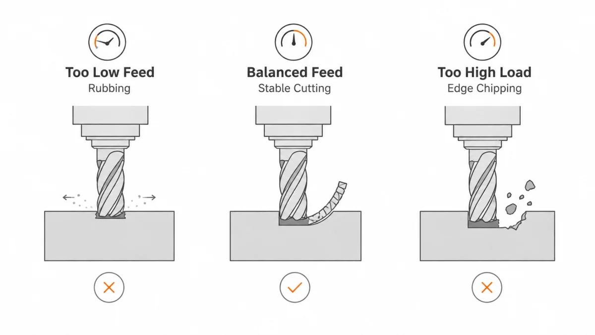
In graphite machining, spindle speed should not be adjusted in isolation. Feed rate and tooling should be evaluated at the same time because all three factors must work together.
Our Speed, Feed and Tooling Controls
| Control Point | Common Failure Pattern | Target Condition |
|---|---|---|
| Spindle Speed | Excessive rpm with a light feed causes rubbing instead of real cutting, then heat builds up | Matched speed and feed, verified on the first article |
| Feed Rate | Too much feed pressure creates heat, rough finish, and fast tool wear | Feed matched to spindle speed and the specified graphite grade |
| Tooling | Incorrect tool type causes rapid wear, edge chipping, and unstable dimensions | Our tooling review matches sharp carbide, diamond-coated carbide or PCD to the grade, geometry, quantity, finish, tolerance and tooling cost, together with dust extraction. |
The first foundation is tooling. Sharp carbide can be suitable for prototypes, small batches, and many general graphite operations, while diamond-coated carbide or PCD becomes more attractive when abrasive wear, repeated production, fine features, dimensional stability, and tool-change cost justify it. Whichever route is selected, reliable dust extraction is required because recut dust can affect the tool path, surface finish, and dimensional accuracy.
Diamond-coated tools generally provide stronger edge-retention potential than uncoated carbide in abrasive graphite cutting, but the usable-life difference is not a fixed multiple. It must be established under the actual grade, tool geometry, engagement, extraction, surface target, and replacement rule.
The second foundation is the relationship between feed rate and spindle speed. If the feed is pushed too hard, even a conservative spindle speed can still generate too much heat. If the spindle runs too fast while the feed is too light, the tool rubs the graphite instead of cutting it. Rubbing creates heat, damages finish quality, and wears the tool faster.
The objective is a stable cut that limits heat buildup, protects edges, holds tolerance, and extends tool life—not simply the highest rpm or feed.
Three Parameter Mistakes That Commonly Destabilize the Cut
The first mistake is raising spindle speed to “polish” the surface. On graphite, that can create rubbing. A smoother finish usually comes from the right finish pass, tool condition, feed match, and dust removal — not simply higher rpm.
The second mistake is reducing feed too much because graphite looks fragile. A feed that is too light does not always protect the part. It can make the tool slide and rub, which creates heat and roughness.
The third mistake is using one parameter set for every graphite grade. Dense fine-grain graphite, ultra-fine high-purity graphite, medium-grain graphite, and lower specific gravity porous grades do not machine the same way. Chip formation, heat conduction, and edge behavior all change with the material.
Add engagement to the speed/feed model. Feed per tooth describes the cut taken by each edge, while radial width and axial depth set total load and dust volume; a full slot and a light finishing pass therefore need different treatment even at the same feed per tooth.
| Symptom | Parameter relationship to check first | Evidence | Our corrective-action review |
|---|---|---|---|
| Rubbing or glazed surface; check whether chip load is too low for the actual tool, grade, and rpm | Feed per tooth too low for rpm or tool edge no longer sharp | Fine powder, heat, polished tracks, rapid edge wear | Our team reviews chip load, tool replacement, runout and engagement against the approved process. |
| Random edge chipping; review excessive radial engagement, unsupported exit, or loss of tool sharpness | Chip load/engagement too high or exit unsupported | Damage concentrated at tool exit or thin section | Our review covers local engagement, cutting sequence and support at the damaged feature. |
| Dust packed in slot | Evacuation insufficient for depth and material-removal rate | Recut marks, rising spindle load, inconsistent slot width | Our review covers extraction, depth per pass and the available debris-removal path. |
| Dimension drifts across lot | Tool wear, offset drift, or measurement inconsistency | Monotonic trend from first-off to later parts | Our team verifies tool condition and the datum before accepting an offset correction. |
| Good roughing, poor finish | Finishing allowance, tool condition, or final chip load unsuitable | Rough stock removed correctly but edge/surface degrades on last pass | Our finishing plan defines the tool and controlled stock allowance. |
Surface Finish Comes From Process Discipline
We use surface inspection to check process stability. Microchipping, sandy texture, glazing or irregular marks trigger a review of feed per tooth, spindle speed, engagement, tool condition, runout, support and dust recutting.
Trying to finish everything in one aggressive pass usually creates more problems than it solves. For precision components, multiple finish passes with stable parameters often give a cleaner result than one heavy cut. This is especially important on thin walls, fine details, sharp edges, and parts that require consistent dimensions.
Our objective is efficient production with stable cutting load, heat and dust control from roughing through finishing.
Surface finish in graphite is the visible result of material structure and the last stable cutting events. A very low feed is not always a finishing strategy. If the edge rubs, the surface can look smeared or sandy even though the machine moves slowly. A sound finishing route uses a suitable finishing tool, consistent stock allowance, stable entry and exit, and extraction that limits recutting of loose particles.
Finish and dimensions must be inspected together. The graphite drawing-review guide covers functional surfaces, datum control, hole position, wall thickness, and edge risk. The thin-wall and small-hole guide explains why access, support, and breakout control must be reviewed before a surface-finish value is accepted. A generic Ra value is not enough when edge condition or pore exposure is also functional.
Dust Extraction Is Part of the Machining Setup, Not an Accessory
Dust control is a required part of a graphite-machining process because graphite dust can affect the machine, toolpath, part cleanliness, inspection surfaces, maintenance burden, and occupational working environment.
A proper graphite machining setup should include consistent dust extraction close to the cutting zone. The system must remove fine particles before they accumulate around the toolpath or settle back onto precision surfaces. For higher-speed or longer machining cycles, extraction stability becomes even more important.
Good dust removal supports three results at the same time:
- It captures loose particles near the toolpath and reduces the chance that dust will be recut.
- It protects the machine, tool interfaces, workholding, and measurement surfaces from particle accumulation.
- It supports cleanliness and occupational exposure control when capture performance, enclosure, maintenance, and work practice are verified.
When extraction is weak, loose particles can be recut, settle on critical surfaces, contaminate inspection, and accelerate process instability. Tool selection and extraction must therefore be managed together, while neither one substitutes for a correct chip load, engagement, support, and tool-change rule.
Extraction performance is verified at the cutting zone, not assumed from the dust collector nameplate. Long hoses, small branches, filter loading, leaks, and an open enclosure can reduce capture. The manufacturing record should identify the machine, extraction connection, and cleaning routine used for the approved process. Occupational exposure remains a facility responsibility and requires appropriate assessment under applicable rules.
The graphite machining challenges guide explains how dust affects measurement and workholding. The packaging and logistics article shows why the cleanliness state must be protected after machining instead of being lost during storage and shipment.
The 15 mg/m³ total and 5 mg/m³ respirable values cited in this article are U.S. OSHA references associated with synthetic graphite or particulates not otherwise regulated. They are not a universal global graphite-machining standard. Each facility must confirm whether the material is synthetic or natural graphite, review the SDS, identify the governing jurisdiction, assess exposure, and verify enclosure, extraction, housekeeping, maintenance, and work practice.
Application-Based Graphite Machining Parameters
There is no universal correct speed for every carbon or graphite part. A large EDM electrode, a thin semiconductor-related component, a battery-process part, and a large mold or die component can require different named grades, tools, engagement limits, inspection plans, and cleanliness controls.
The graphite grade, grain size, density, purity, geometry, tolerance requirement, and surface finish target all change the parameter window.
Practical Machining Parameters by Graphite Application
| Application | Illustrative material-selection approach | Main Machining Priority | Illustrative process approach |
|---|---|---|---|
| EDM electrode — establish finishing parameters from the named grade, feature scale, tool, and first-off result | Named EDM grade selected by detail, wear, finish, strength, particle size, and electrode strategy | Surface finish and detail accuracy | Start from verified chip load and engagement; separate roughing and finishing; confirm detail retention on first-off parts |
| Semiconductor-related component — identify thin walls and critical tolerances from the drawing and process context | Named grade or approved property envelope selected for purity, grain structure, strength, coating route, and cleanliness | Tight tolerance and no chipping | Use stable support, sharp tooling, controlled engagement, verified extraction, and a customer-approved first-off inspection plan for critical features |
| Battery-process graphite parts — confirm purity or ash basis and define a risk-based pilot-lot inspection frequency | Named grade selected for purity or ash, strength, pore structure, dimensions, and downstream service | Dimensional consistency and thermal stability | Establish speed, feed, engagement, extraction, and sampling from the drawing and approved pilot-lot evidence |
| Large Mold / Die | Named grade selected by feature scale, strength, stock size, removal allowance, finish, and service requirement | Material removal rate | Use a dedicated roughing route and leave a consistent finishing allowance; validate edge and dimensional stability |
This is an illustrative selection approach only. Final material must be identified by a named grade or an approved property envelope. The application label alone does not determine grain size, density, purity, tool, speed, feed, engagement, or sampling.
For EDM electrodes, detail retention depends on the named grade, electrode geometry, strength, particle size, tool edge, engagement, and finishing allowance. Official grade portfolios include multiple superfine and ultrafine options for different combinations of roughing, finishing, wear, strength, and detail; no single “fine-grain, high-density” rule covers every electrode.
For semiconductor-related components, grade selection must separately address purity, grain and pore structure, strength, anisotropy, coating or purification route, and cleanliness. Tight dimensions still require supported geometry, sharp tooling, controlled engagement, verified cleaning, and an agreed inspection plan.
For battery-related graphite parts, the drawing and downstream service should define purity or ash limits, dimensions, surface condition, contamination controls, and sampling. Extraction protects cleanliness and limits dust recutting; dimensional stability still depends on the named grade, support, chip load, engagement, tool condition, and inspection evidence.
For larger mold, die, and tooling components, stock size, feature scale, strength, removal allowance, and surface target determine whether a superfine, fine-grain, or other approved grade is appropriate. Roughing and finishing should use separate parameter windows, with a controlled finishing allowance and final edge inspection.
QDZRT Graphite serves industrial customers who require graphite materials and custom-machined components for EDM, sealing, thermal management, conductive parts, high-temperature fixtures and drawing-based precision applications.
Graphite machining is not slower metal machining. It is its own discipline. Once that is understood, the process becomes much more predictable: cleaner edges, better surface finish, longer tool life, and more reliable graphite components.
Application-based parameters begin with failure sensitivity. An EDM roughing electrode can accept a different surface and edge strategy from a semiconductor fixture, a furnace support, or a sealing component. The process owner should first identify the functional features, then approve the grade, roughing route, finishing route, tool-life rule, and inspection frequency. The final parameter sheet belongs to the part revision and should not be copied automatically to a different grade or geometry.
Related application references include EDM and precision tooling, custom graphite parts in industrial applications, and the drawing tolerance confirmation guide.
The Six-Control Parameter Chain
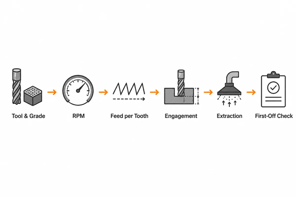
A repeatable graphite-machining route links six controls in order: Tool & Grade → RPM → Feed per Tooth → Engagement → Extraction → First-Off Check. A parameter is not approved by itself. The process record should show how the named grade, tool diameter, flute count, spindle speed, chip load, radial and axial engagement, extraction setup, and first-off result work together for the specific part revision.
How We Cross-Check the Approved Feed Calculation
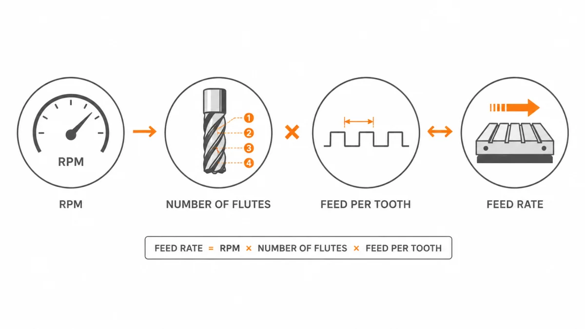
Our engineering check uses feed rate = spindle speed × flute count × feed per tooth to confirm that the approved inputs are consistent. Grade, tool, engagement, machine, extraction and feature conditions remain part of the process review; the equation alone does not validate a cutting condition.
| Case | RPM | Flutes | Feed per tooth | Calculated feed |
|---|---|---|---|---|
| Approved finishing case | Approved rpm | 2 | Approved feed per tooth | Calculated from approved inputs |
| Alternative flute-count check | Approved rpm | 4 | Approved feed per tooth | Recalculate from approved inputs |
| Approved roughing case | Approved rpm | 2 | Approved feed per tooth | Calculated from approved inputs |
| Low-chip-load diagnostic case | Recorded rpm | 2 | Recorded low chip load | Calculated diagnostic feed |
| High-load diagnostic case | Recorded rpm | 2 | Recorded high chip load | Calculated diagnostic feed |
The diagnostic rows contain no transferable settings. An actual cut must be validated through first-off inspection, tool condition, spindle load where available, surface appearance, edge survival, and dimensional trend.
Parameter Transfer Rules for Repeat Production
- Our repeat-order record retains the approved tool, coating, diameter, flute count, overhang, holder, program revision, grade, blank orientation and extraction setup.
- Our team reassesses speed and feed when diameter, grade, engagement, feature support or machine changes.
- We review revalidation needs after changes to material, tooling source, fixture, extraction or drawing revision.
- Our inspection follows wear-sensitive features alongside cycle time.
- We retain first-article results and the reasons for offset or tool-life changes.
For manufacturing and repeat-order controls, see our custom graphite manufacturing guide and OEM customization options.
Frequently Asked Questions
How does QDZRT Graphite approve machining parameters?
We review the grade, drawing, tool diameter, flute count, engagement, machine rigidity, coating, extraction and feature support, then check the first article. The approved record connects speed and feed with depth, width, tool identity and the verified geometry.
Is slower always safer for brittle graphite?
No. Reducing feed too far while keeping high rpm can make the edge rub instead of cut. Rubbing creates fine powder, heat, poor finish, and rapid wear. Safety comes from a stable chip load, limited engagement, sharp tooling, support, and extraction. A fragile feature may require a different sequence or support, not simply slower motion.
Why are diamond-coated tools used for graphite?
Graphite is abrasive, so tool-edge retention is important for long runs and fine details. Diamond-coated carbide can provide longer usable life than uncoated carbide in suitable applications. It is not always the best choice for every diameter or geometry. Coating quality, edge radius, tool cost, runout, and the required feature determine the choice.
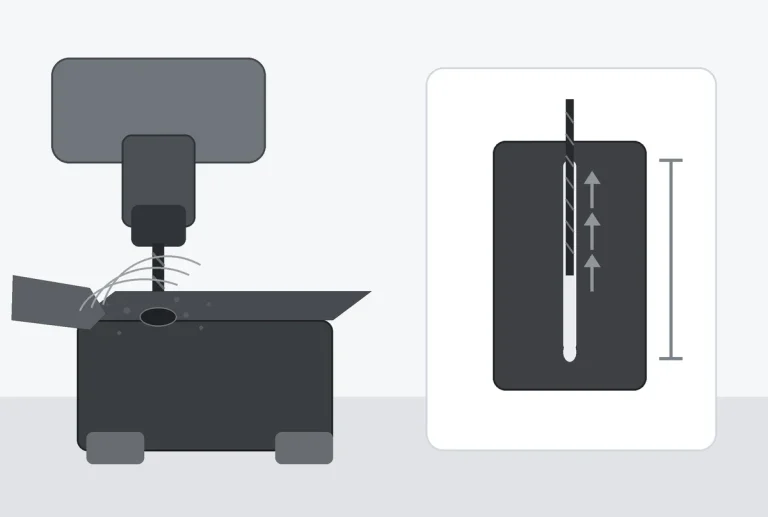
How is drill breakout reduced in graphite?
Our drawing review checks hole-to-edge distance, remaining wall thickness and the required entry and exit condition. The process plan then addresses compatible backing support, tool sharpness, feed, runout and dust removal, with inspection against the approved drawing.
Can metal cutting data be converted directly to graphite?
No. A calculation may convert surface speed or feed units, but it does not transfer the material-removal mechanism, dust evacuation, edge behavior, workholding, or tool wear. Metal-machining experience can inform machine operation, but the graphite parameter set must be developed around the actual grade and feature risk.
How often are parameters revalidated?
Revalidation is required when the grade, blank source, tool, coating, machine, fixture, extraction, program, or drawing changes in a way that may affect the result. Stable repeat production can continue from the approved record, with interval checks confirming that tool wear and dimensions remain within the control plan.
What manufacturing information supports the first article?
Our process record can link material grade and lot, blank size, machine, tool and holder, speed, feed, flute count, engagement, extraction, program revision, cycle time, dimensions, surface condition, edges and tool wear. The order and inspection plan define the records supplied to the customer.
References & Sources
- NIST Dimensional Metrology Publications — Supports trend-based inspection and measurement-method control.
Request a Drawing-Based Manufacturing Review
Send QDZRT Graphite the part application, graphite grade or required properties, drawing revision, quantity and critical dimensions through our contact page. After our reply, drawings and inspection requirements can be shared by email or another agreed channel. We review material, manufacturability, inspection and packing as part of the quotation.