Deep-hole drilling in graphite looks simple on a drawing: one diameter, one depth, perhaps one positional tolerance. In production, the difficulty is not the existence of the hole but the sequence required to create, clean, and verify it without chipping the entry or exit, losing straightness, trapping dust, or promising a tolerance that cannot be inspected reliably.
The right approach is to treat the hole as a process chain. Define the geometry and access, choose a tool with enough stiffness and reach, control chip evacuation, plan the drilling sequence, protect the breakthrough region, clean the bore before measurement, and confirm that the inspection method can actually reach the feature.
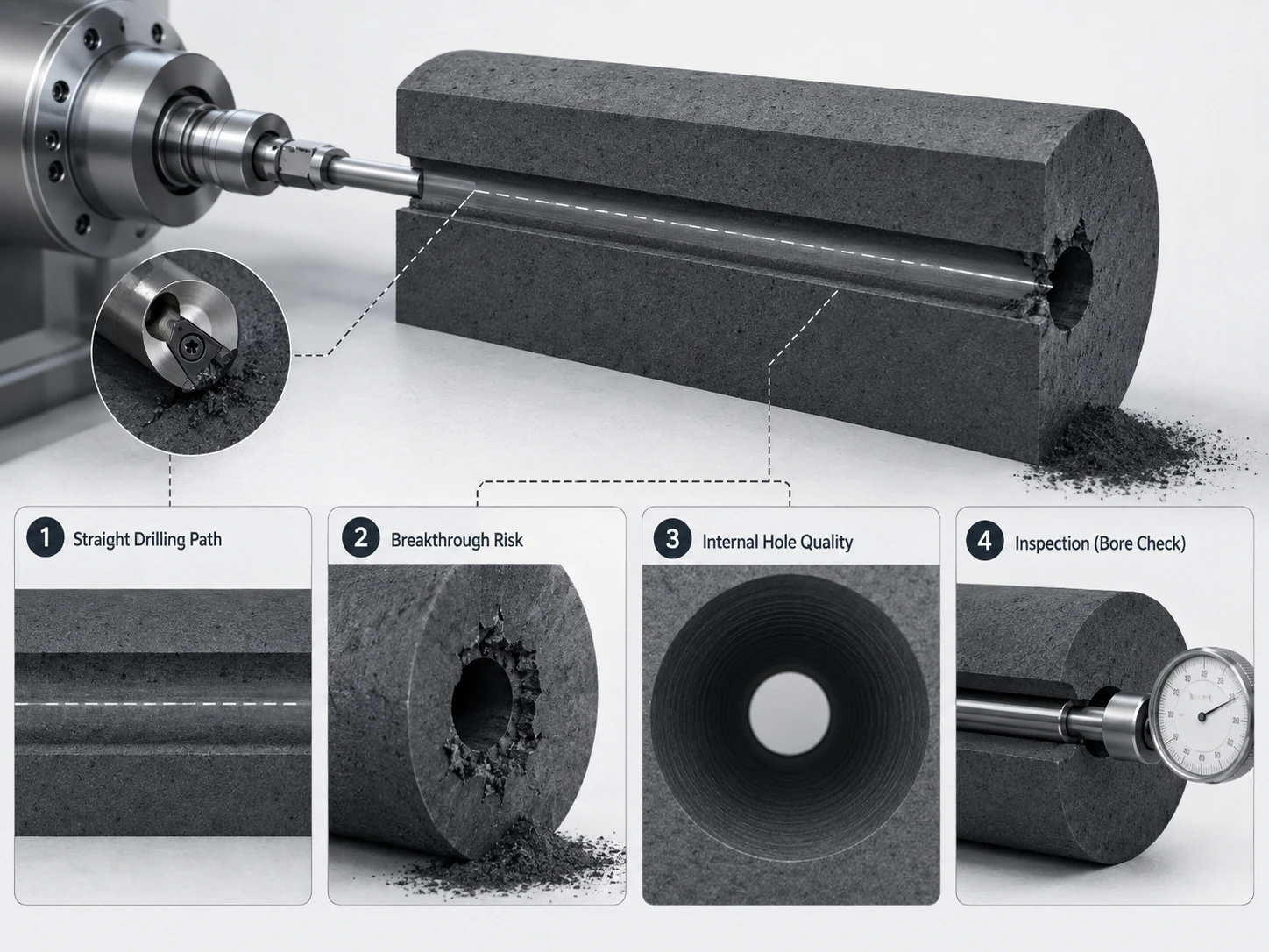
Define the Hole by Depth, Diameter, Entry, Exit, and Access
A deep hole should never be defined by diameter and total depth alone. The machining engineer also needs to know whether the hole is through or blind, whether one or both ends are accessible, whether the entry face is flat or angled, whether the exit breaks into another feature, and which surfaces can be used for alignment and inspection.
Depth-to-diameter ratio is useful as a description, but it should not be converted into a universal accept/reject threshold without context. Tool diameter, tool material, flute design, reach, spindle condition, graphite grade, geometry around the hole, and inspection access all change the practical difficulty.
Entry geometry matters because the drill needs a stable start. A hole that begins on a curved face, narrow rib, interrupted surface, or edge is more sensitive to wandering or local chipping than a hole starting on a broad, well-supported flat face.
Exit geometry matters just as much. If the drill breaks through a thin wall or exits beside a fragile edge, the remaining material may chip. If it opens into an internal cavity, loose graphite particles can remain trapped unless the cleaning route is planned.
Blind holes create a different problem. The bottom geometry, required usable depth, and inspection method need to be clear. A drawing that calls for a flat-bottomed functional zone may require a different tool sequence from a simple drilled depth.
Before quoting, the hole should be described using at least these fields:
- nominal diameter;
- total depth or through condition;
- entry-face geometry;
- exit condition or blind-bottom requirement;
- positional tolerance and datum system;
- diameter tolerance;
- straightness or coaxiality requirement if functionally necessary;
- surface requirement inside the bore if any;
- access for cleaning and inspection;
- relationship to nearby holes, pockets, threads, or thin walls.
The more demanding the geometry, the more important it is to resolve these fields before machining starts.
Tool Reach, Stiffness, and Chip Evacuation
Long tool reach reduces stiffness. Even in a material that machines readily, a slender tool can deflect, vibrate, or follow a less stable path if the setup is not controlled.
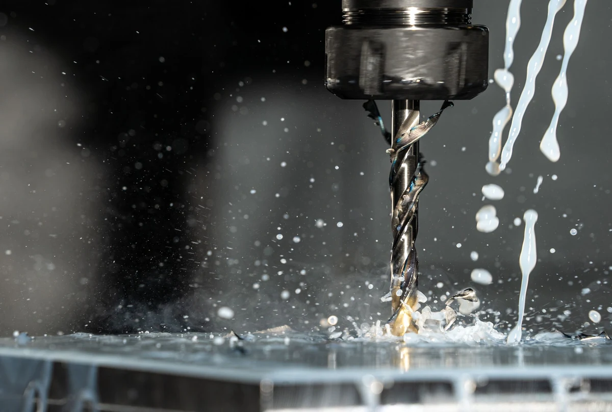
The shortest practical tool should be used for each stage. If a hole can begin with a shorter, stiffer tool and only later require a long-reach tool, the process may be more stable than using maximum reach from the first contact.
Tool diameter and flute design influence both stiffness and dust removal. Graphite drilling produces fine particulate rather than the long metal chips seen in many metallic materials, but the material still needs a path out of the hole. If dust packs in the flute or blind bottom, cutting conditions can change and the tool can rub or bind.
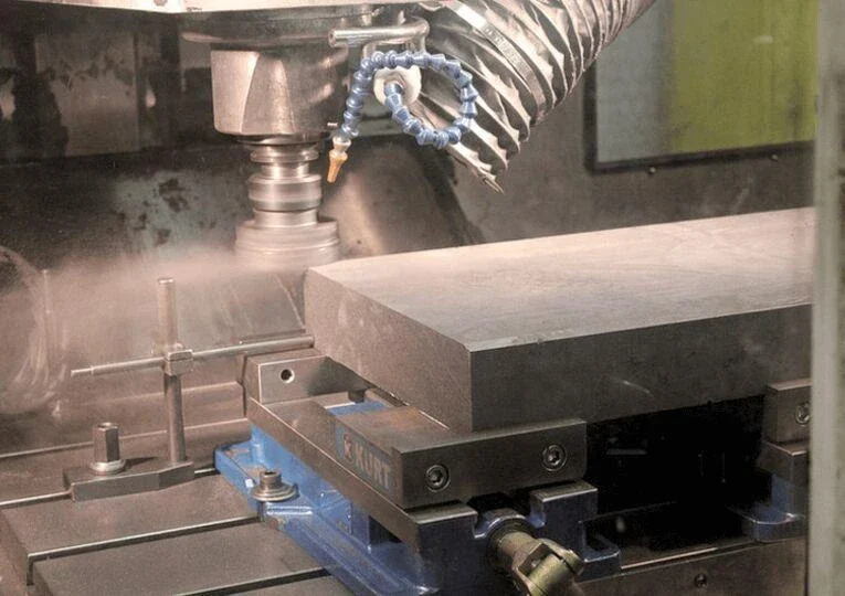
Extraction around the entry can help remove material as it exits the bore, but the effectiveness depends on the machine enclosure and capture geometry. The shop should not assume that room-level dust extraction automatically clears a deep bore.
Tool runout also matters. Small-diameter deep holes are particularly sensitive to spindle, holder, collet, and tool condition. A tool that appears straight visually can still create an oversized entry, tapered bore, or unstable path if runout is excessive for the feature.
Before the operation, inspect the tool and holder, minimize unnecessary stick-out, verify the programmed length, and ensure that the tool-change and machine-clearance path cannot cause a collision with the workpiece or fixture.
Plan the Drilling Sequence Instead of One Continuous Cut
A deep hole is usually better treated as a sequence of controlled steps than as one uninterrupted motion. The exact sequence should be established for the tool, graphite grade, depth, and machine rather than copied from a universal peck-drilling table.
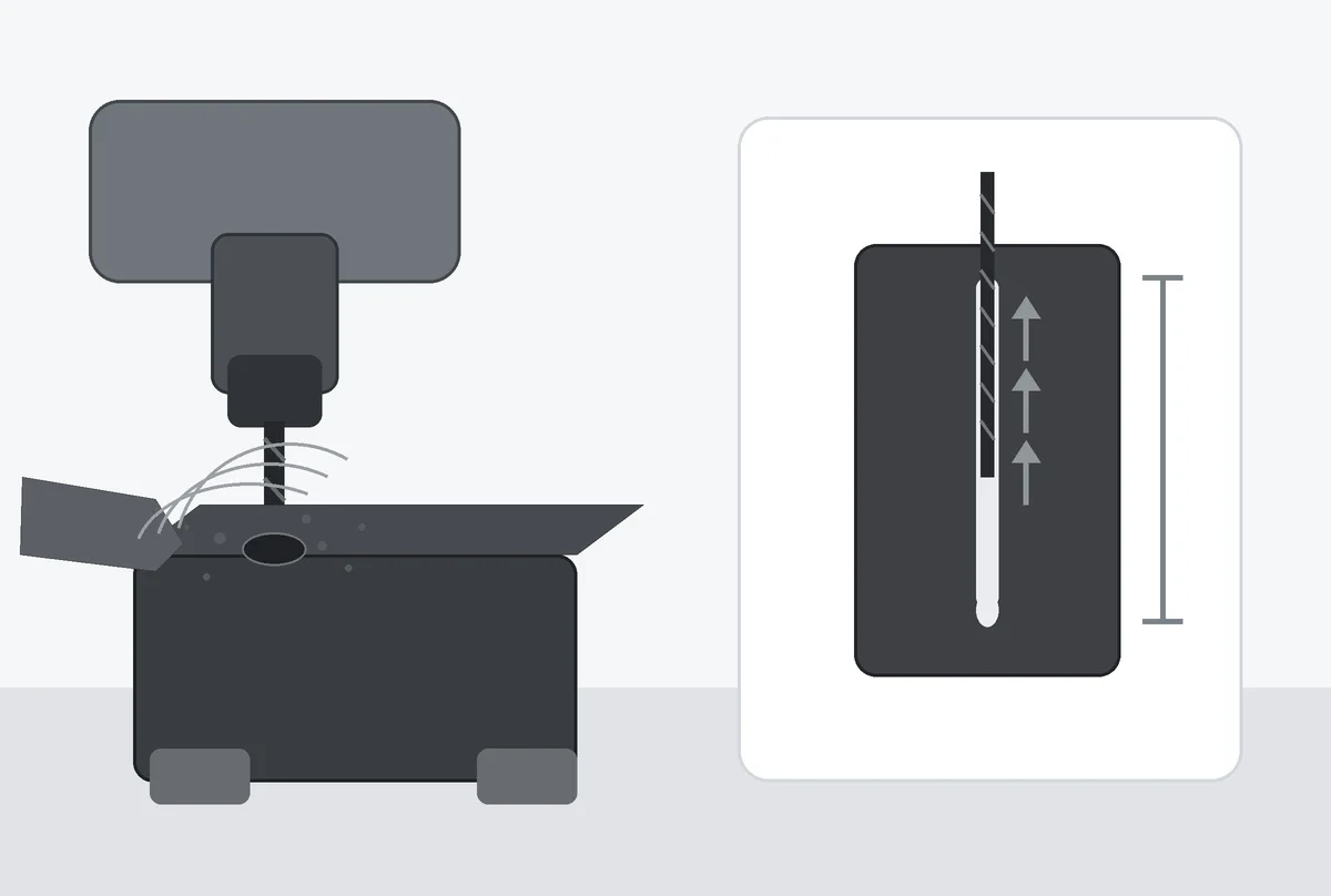
A typical strategy may include a stable starting feature, progressive drilling with periodic withdrawal or clearance, intermediate cleaning, and a final pass or finishing operation where the tolerance requires it. The number and depth of increments depend on actual process behavior.
The purpose of staged drilling is not merely to reduce cutting force. It creates opportunities to remove graphite dust, inspect tool condition, confirm that the process remains stable, and avoid carrying packed material deeper into the bore.
For very deep features, the operation can sometimes be divided from two ends if the drawing and tolerance allow it. That can reduce tool reach, but it creates a new alignment problem where the two bores meet. The decision should therefore be based on datum control and functional requirements, not convenience alone.
If several deep holes are present, sequence them to preserve workpiece stiffness. Machining one hole may reduce the section supporting another. A program that is efficient in tool-change count is not necessarily the most robust sequence for a fragile graphite component.
The process plan should also consider when external contours are machined. Drilling a deep hole while the surrounding blank is still relatively stiff may be safer than drilling after large pockets or thin walls have already been created.
Support the Entry and Breakthrough Zones
Entry and breakthrough are the two locations where a deep-hole operation is most visibly vulnerable to edge damage.
At the entry, the drill should start on a stable surface with sufficient local support. If the final design includes a chamfer or counterbore, the sequence should be chosen so that the drill still has a controlled start and the edge is protected during later operations.
At breakthrough, cutting forces change as the remaining material becomes thin. A through-hole that exits into open space can chip the edge if the process is too aggressive or the exit geometry is poorly supported.
Where the design allows, temporary backing or sacrificial support may reduce exit damage. In other cases, changing the approach direction or leaving additional stock until after drilling can protect the feature. The correct method depends on the part geometry and contamination restrictions.
If the hole exits into another machined cavity, the intersection should be reviewed. A sharp internal intersection can shed loose particles or create a fragile edge that is difficult to inspect. A customer drawing may need an intentional relief, radius, or edge note if the intersection is function-critical.
Breakthrough should never be judged only by whether the drill emerged. The exit edge, positional relationship, chipping condition, and bore cleanliness should all be checked where they matter to function.
Clean the Hole Before Measuring It
Graphite dust can remain inside a deep hole after the tool is removed. Measuring before cleaning can give false diameter readings, interfere with gauges, or hide damage at the bottom or exit.
The cleaning method should match the application and site rules. Vacuum extraction, controlled gas, brushes, dedicated cleaning tools, or customer-specified methods may be used, but the cleaning step should remove particulate rather than simply relocate it.
Blind holes deserve particular attention because the bottom can retain fine dust. If the hole later receives a pin, tube, threaded insert, fluid path, or electrical component, retained particulate can interfere with assembly or cleanliness.
For high-purity or vacuum applications, the cleaning method itself can be a contamination source. Tools, hoses, cloths, compressed-gas systems, and storage containers should therefore be compatible with the customer’s cleanliness requirement.
A practical process includes cleaning before in-process measurement, cleaning again after all adjacent machining is complete, and protecting the bore from recontamination during final handling and packaging.
If the customer requires evidence of cleanliness, the verification method should be defined at quotation stage. “No visible dust” and a formal particle or contamination requirement are not the same acceptance condition.
Inspection Access Can Limit the Tolerance You Can Prove
A hole can be machined more accurately than it can be measured if inspection access is poor. That creates a dangerous specification: the supplier may believe the process is capable, but neither side has reliable evidence at the required depth.
Diameter can sometimes be checked near the entry with standard gauges while the deeper section remains unverified. Straightness, taper, position, bottom geometry, or internal surface condition may require dedicated metrology.
The drawing should therefore distinguish what needs to be controlled from what can actually be measured. If full-depth diameter is critical, the customer and supplier should agree on a verification method appropriate to the bore size and depth.
Coordinate measurement may verify entry position and external datums but not necessarily the complete internal path. Bore gauges, air gauging, optical methods, pins, dedicated fixtures, or other methods may be applicable depending on the feature. No single method suits every graphite deep hole.
Inspection access also affects tolerance cost. A very tight positional or straightness requirement may require special tooling, staged inspection, or process qualification. If the function does not require that level of control, the drawing should not impose it simply because the CAD model is exact.
For blind holes, useful depth and bottom location should be defined carefully. Tool-point geometry, debris at the bottom, and the inspection probe can all influence the reported depth.
Feed the Inspection Result Back into the Next Setup
Deep-hole machining should become more predictable over repeat production. That only happens if inspection data are connected to the machining setup.
If the bore consistently drifts in one direction, investigate tool runout, holder condition, workholding, entry geometry, spindle alignment, tool wear, and sequence. Do not compensate blindly in the program until the cause is understood.
If exit chipping appears only after a certain number of parts, tool wear or changing support conditions may be involved. If the first part chips, the entry/exit strategy or geometry may be the real problem.
Record enough information to compare batches:
- part and drawing revision;
- graphite grade or material lot where relevant;
- tool type, diameter, reach, and tool ID;
- holder and machine;
- drilling sequence;
- cleaning method;
- measured diameter and position at defined locations;
- exit-edge condition;
- tool-change point and reason;
- any deviation or process adjustment.
This turns deep-hole drilling from a one-time operator skill into a repeatable manufacturing process.
Deep-Hole Risk Map
Before cutting
Check hole geometry, access, datum scheme, surrounding wall thickness, tool availability, reach, inspection method, and whether the hole should be drilled before or after other material is removed.
During entry
Control the start surface, tool runout, local support, and any starting feature that helps the drill establish position.
During depth progression
Monitor dust evacuation, tool condition, machine load trends where useful, program sequence, and whether periodic withdrawal or cleaning is required.
At breakthrough
Protect the exit edge, reduce the risk of local chipping, confirm the relationship to nearby cavities, and inspect the remaining wall.
After drilling
Clean the bore completely before dimensional verification, inspect entry and exit, confirm accessibility of the specified measurement, and protect the finished hole from later contamination.
When a Drawing Should Be Reviewed Before Machining
Not every deep-hole requirement should be accepted without discussion. DFM review is especially important when:
- the hole is very small relative to depth;
- the hole exits through a thin wall;
- the entry is on a curved or interrupted surface;
- multiple deep holes intersect;
- two-ended drilling would be required to reach the feature;
- straightness or position is very tight over a long depth;
- the bore must be measured at full depth but no inspection method is defined;
- the hole is close to a fragile edge, thread, pocket, or sealing surface;
- cleanliness requirements make normal dust-removal methods unsuitable.
Raising these issues before machining is not a refusal to manufacture the part. It is how the supplier separates a controllable process from an unsupported promise.
How QDZRT Graphite Approaches Deep-Hole Features
QDZRT Graphite can review customer drawings for hole access, surrounding material, tool reach, breakthrough risk, machining sequence, cleaning, and inspection access before production.
For repeat orders, the approved process can retain tool and inspection history so that later batches begin from actual evidence. Where the customer changes depth, diameter, nearby geometry, material grade, or tolerance, the hole should be reviewed again because the previous process may no longer apply.
Customers requesting a quotation should identify which hole characteristics are function-critical. If the bore only provides clearance, an unnecessarily tight full-depth tolerance can add cost. If the bore carries a tube, electrode, pin, flow path, or alignment feature, explain that function so the machining and inspection plan can focus on the correct risk.
Use Repeat-Order Evidence to Stabilize the Bore Process
For recurring components, retain the drawing revision, material identity, tool and holder information that affects the bore, inspection results at defined locations, cleaning record, and any entry or exit observations. The purpose is not to preserve every machine setting forever; it is to preserve the variables that explain whether the same feature was produced on the same basis.
When a later batch shifts, compare the new result with that baseline before changing several variables at once. A positional trend, recurring exit defect, or cleaning problem becomes easier to diagnose when the team can see whether the tool reach, holder, graphite grade, surrounding geometry, inspection method, or process sequence changed.
Review Geometry Changes as a New Bore Condition
A proven drilling route should be rechecked when the customer changes diameter, depth, entry face, exit condition, nearby pocket, wall thickness, datum scheme, or inspection requirement. A small CAD revision can alter tool reach, local support, breakthrough behavior, or access to the measuring feature. Carrying the previous process forward without review can hide the fact that the manufacturing problem has changed. Link the approved bore process to the drawing revision so a repeat order uses prior evidence without assuming that every later geometry is equivalent.
Deep-hole quality is easier to diagnose when the surrounding process controls are separated. The graphite dust-control guide covers machine cleanliness and debris management, while the surface-finish guide covers how to specify and verify texture where the bore surface is function-critical.
References and Sources
ISO 230-1:2012 — Test code for machine tools — Part 1. Provides geometric-accuracy testing context for machine tools; deep-hole performance still depends on the actual tool, setup, graphite, and drilling process.ISO 286-1:2010 — ISO code system for tolerances on linear sizes — Part 1. General dimensional-tolerance terminology useful when a drawing controls bore size or mating fit.