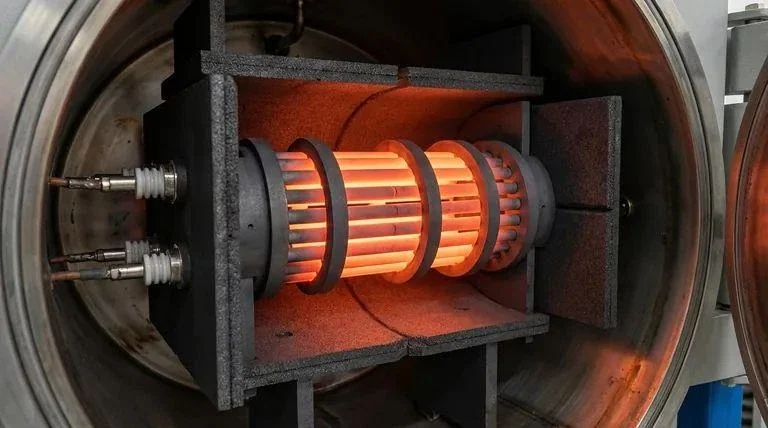
A graphite heater is not simply a hot graphite part. It is an electrical resistance component whose geometry, material properties, connections, atmosphere, thermal expansion, and mechanical support all affect how power is converted into heat. A heater that reaches the target temperature once can still be a poor production design if it develops local hot spots, unstable contacts, repeated cracking, excessive dimensional change, or short service life.
Start with the furnace electrical and thermal requirements, then turn them into a controlled current path and manufacturable graphite geometry. Do not copy a current-density, temperature, or resistance value from another furnace and treat it as universal.
Start with Power, Voltage, Temperature, and Atmosphere Requirements
The electrical design begins with the furnace power system. The designer needs the available voltage range, required heating power, control method, heater arrangement, operating temperature profile, atmosphere, and the thermal load of the furnace.
Power and voltage define the resistance range the heater system must provide. That does not mean the heater can be designed from one equation alone. The effective electrical path includes the graphite body, local cross-sections, joints, terminals, contact areas, multiple heater elements, and the way those elements are connected in the furnace.
Temperature should be described as a complete cycle. Record the start condition, ramp, soak, cooling sequence, dwell frequency, and whether the furnace repeatedly moves between room temperature and high temperature or stays hot between production cycles. Repeated thermal cycling can create a different mechanical problem from steady high-temperature operation.
Atmosphere is equally important. Graphite heaters are commonly associated with vacuum or inert environments because oxidation becomes a major concern when hot graphite is exposed to oxygen. But a furnace described as “vacuum” can still include pump-down, purge, process gas, leakage, controlled venting, and air exposure during unloading. The heater should be evaluated against the complete sequence rather than one atmosphere label.
A heater design input sheet should therefore include:
- furnace chamber geometry and usable hot-zone dimensions;
- power supply voltage and control range;
- required total heater power;
- target thermal cycle and maximum process temperature;
- vacuum, inert-gas, or other process atmosphere;
- heater arrangement and number of electrical circuits;
- terminal locations and connection constraints;
- insulation arrangement and nearby shields;
- workpiece load and production loading pattern;
- expected cycling frequency and maintenance access.
These inputs define the engineering problem; there is no useful universal “recommended heater value” outside the actual furnace.
Electrical Resistance Is a Geometry-and-Material Problem
The resistance of a graphite heater depends on the electrical resistivity of the selected material and on the geometry of the current path. Length, cross-sectional area, slots, bridges, transitions, parallel paths, and connections all contribute.
That makes geometry part of the electrical specification. If a heater is redesigned to use less graphite, improve machining access, or fit a changed chamber, resistance distribution can change even if the same graphite grade is used.
Graphite grades can differ in resistivity, structure, strength, thermal behavior, purity, and directional properties. If the furnace was qualified with a specific grade, keep that material identity for replacements or use a defined equivalency review.
Datasheet values also need context. Electrical resistivity may be reported with a specific test method, temperature, and orientation. Those values are useful for design and comparison, but they should not be treated as the exact operating resistance of a complete heater at all temperatures.
For repeat production, define how cold resistance is checked before installation, how circuit symmetry is assessed, and what change triggers investigation or replacement.
Cross-Section, Current Path, and Local Hot Spots
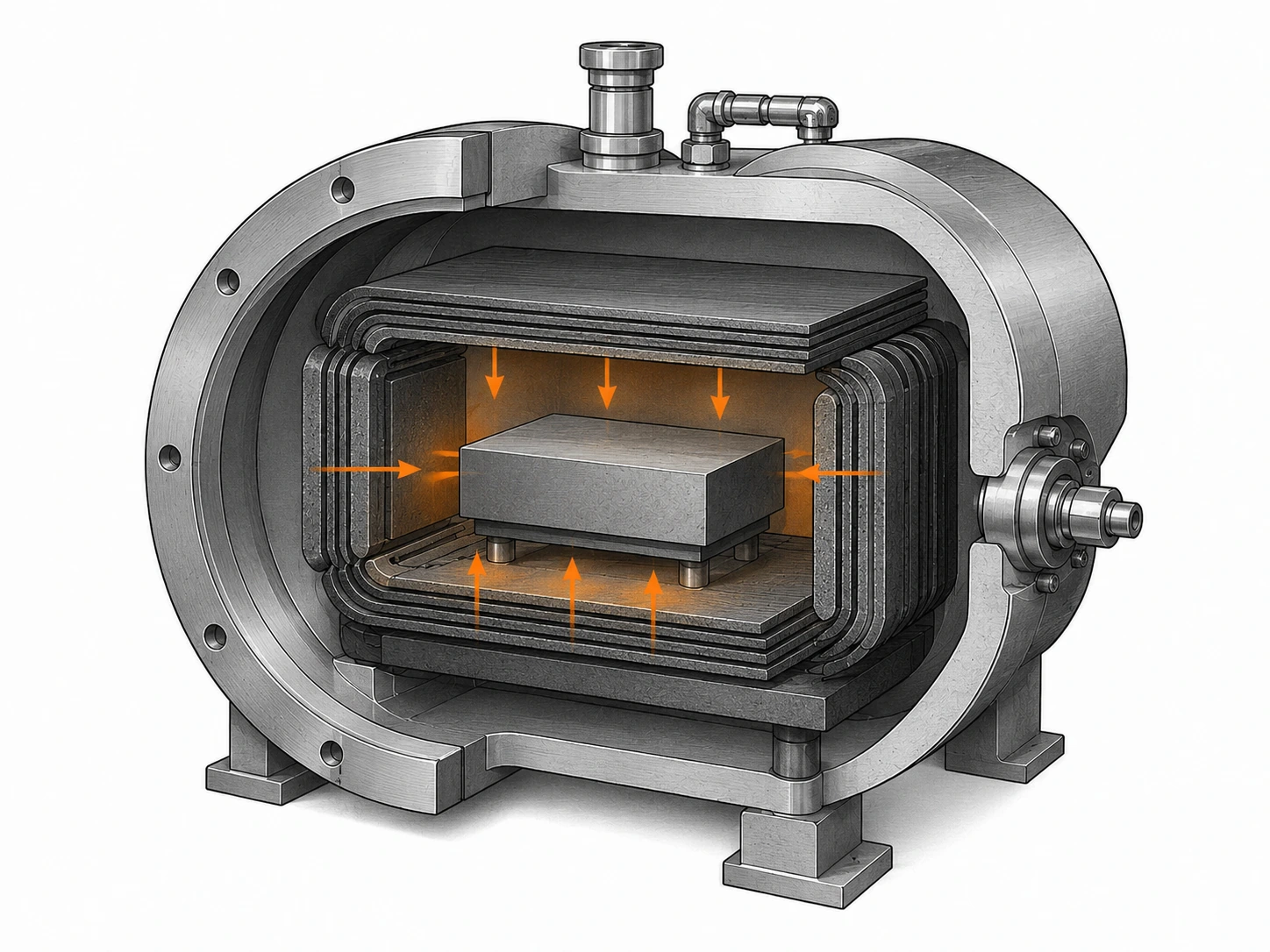
A local reduction in cross-sectional area increases current concentration and can create a hotter region. Heater slots, necks, corners, bolt holes, terminal transitions, and machining reliefs therefore deserve detailed review.
The most dangerous features are often not the visually largest parts of the heater but the narrow bridges that carry the full current. A small dimensional deviation in one of those sections can change the local electrical and thermal condition more than a similar deviation on a broad noncritical surface.
Current-path symmetry is important in multi-leg or multi-zone heaters. If nominally equivalent branches differ in section, length, connection resistance, or contact pressure, one path may carry a different share of current. The resulting temperature imbalance can appear as a furnace-control problem even though the root cause is heater geometry or connection condition.
Corners should be reviewed from both electrical and mechanical perspectives. Sharp transitions can concentrate current and can also create mechanical stress concentration during thermal expansion and handling. The correct corner geometry is design-specific; one universal radius cannot be applied to every heater.
The drawing should therefore identify electrically critical sections. These are the dimensions that deserve tight process control and inspection. Noncritical external surfaces should not receive the same tolerance simply because they are easy to dimension.
A useful hot-spot investigation sequence is:
- confirm the temperature measurement and sensor location;
- compare the heater geometry with the approved drawing;
- check the narrowest current-carrying sections;
- inspect terminal contact and connection surfaces;
- confirm material grade and replacement history;
- verify the power-control configuration;
- inspect insulation, shields, and nearby thermal conditions;
- evaluate oxidation or local surface loss;
- compare the problem location with previous failed heaters.
This sequence avoids replacing the graphite grade before the actual current path has been checked.
Connections and Contact Areas Are Part of the Heater Design
Heater terminals are often treated as accessories, but electrically they are part of the circuit. Poor contact can create local resistance, heating, arcing, surface damage, or unstable furnace performance.
Connection design should define the graphite contact geometry, mating component, clamping method, assembly sequence, allowable movement, and inspection method. The joint must carry current while also accommodating thermal expansion and avoiding excessive mechanical stress on the graphite.
Contact surfaces should be dimensionally controlled and protected from damage. Chipping, contamination, oxidation, deposits, or uneven clamping can reduce effective contact area. A visually small defect at a high-current joint may matter more than a larger cosmetic mark on an isolated part of the heater.
Fasteners and mating materials should be selected by the furnace designer because the joint exists in the electrical, thermal, and atmosphere environment of the furnace. QDZRT Graphite can machine the graphite connection features from a controlled drawing, but the complete joint design must consider the rest of the furnace hardware.
Assembly torque or clamping force should not be invented by the graphite supplier unless the joint has been engineered and qualified as a complete assembly. Too little force can create unstable contact; too much force can damage graphite or restrict thermal movement.
For maintenance, the terminal region should be accessible enough to inspect. If a joint is buried behind insulation or shields, the furnace maintenance plan should define how its condition is verified during shutdown.
Ramp, Thermal Cycling, and Mechanical Constraint
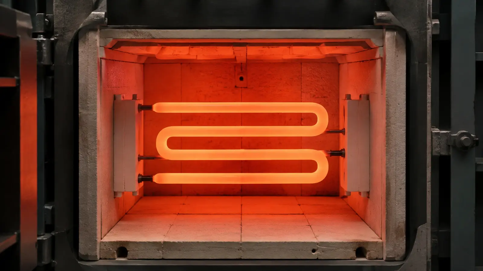
Graphite heaters expand and experience temperature gradients as the furnace heats. The mechanical support system must allow the heater to move as intended without forcing it into bending, tension, or contact with nearby components.
A heater that is rigidly constrained at multiple points can develop stress during expansion. Conversely, a heater with excessive freedom can sag, shift, or contact shields and insulation. The support design therefore needs a controlled balance between location and movement.
Ramp rate is part of the thermal system. A rapid power change can create larger transient temperature differences across sections of the heater, especially around heavy-to-thin transitions or areas with different radiation surroundings. Whether that is acceptable depends on the heater geometry and furnace design; there is no universal safe ramp rate for all graphite heaters.
Repeated cycles also expose handling and installation weaknesses. Small cracks created during assembly may remain unnoticed until thermal cycling propagates them. For this reason, pre-installation inspection and post-failure examination should both include edges, holes, narrow bridges, contact areas, and support interfaces.
Dimensional change should be monitored where it affects clearance. A heater that moves closer to a shield, insulation panel, or neighboring element can change thermal performance or create electrical risk. The drawing package should identify minimum functional clearances, while the furnace owner should control the installed position.
Failure Patterns: Cracks, Hot Spots, Oxidation, and Contact Damage
Failure analysis should begin with the physical evidence. Different damage patterns point to different mechanisms, and replacing the heater without documenting the failed part wastes useful process information.
Cracks near a narrow bridge or abrupt geometry transition may suggest a combination of thermal and mechanical stress. Cracks around mounting or terminal holes can point toward assembly load, constraint, or local damage. A fracture after handling may have little connection to the furnace temperature itself.
Hot spots can leave local surface changes or accelerated material loss. Their causes may include reduced section, electrical imbalance, poor contact, changed insulation, local oxidation, or a control-system issue. The location should be mapped back to the drawing and circuit.
Oxidation damage often appears as section loss, roughened surfaces, thinning edges, or accelerated deterioration at hot areas. The correct investigation includes oxygen exposure, leakage, purge and vent sequence, unloading temperature, and storage conditions—not simply the graphite grade.
Contact damage can include pitting, arcing marks, local erosion, uneven surfaces, or cracking around the terminal. These clues should trigger inspection of the mating component and joint assembly, not only replacement of the graphite part.
A structured failure record should capture:
- heater identification and drawing revision;
- material grade;
- installation date;
- operating cycles or service history;
- failure location on the drawing;
- photographs before disassembly where possible;
- crack or damage orientation;
- terminal condition;
- insulation and shield condition;
- atmosphere abnormalities or leak events;
- recent process or control changes;
- dimensional comparison with a new heater where useful.
Use the failure record to decide whether the next change belongs to geometry, contacts, support, atmosphere, control settings, or the graphite material.
Drawing, Inspection, and Replacement Strategy
A production heater drawing should freeze the electrical geometry that has been qualified. Critical current-carrying sections, slot dimensions, terminal interfaces, datums, support features, and material grade should be controlled explicitly.
Inspection should prioritize the dimensions that affect resistance distribution, fit, and clearance. This is more useful than applying unnecessarily tight tolerances to every machined surface.
Before installation, a replacement heater can be checked for identity, drawing revision, visible damage, critical dimensions, and agreed electrical characteristics. The furnace owner should also inspect mating terminals, supports, shields, and insulation so that a new heater is not installed into the same condition that caused the previous failure.
Replacement strategy should consider whether heaters operate individually or as a matched circuit. If multiple elements are expected to have similar electrical behavior, the maintenance plan may need rules for replacing one element versus a set. That decision belongs to the furnace electrical design and production history.
QDZRT Graphite can machine custom graphite heaters from customer drawings and can review manufacturability, feature risk, blank availability, and inspection access. The furnace electrical design, power settings, atmosphere limits, and qualified operating envelope remain the responsibility of the equipment and process design.
Heater Design Input Sheet
Before requesting a quotation, consolidate the following information:
| Design Input | What to Provide | Why It Matters |
|---|---|---|
| Electrical system | Voltage range, circuit arrangement, target power | Defines required heater resistance behavior |
| Thermal process | Ramp, soak, cooling, target temperature | Frames thermal gradients and cycling |
| Atmosphere | Vacuum/inert sequence and air-exposure stages | Controls oxidation risk context |
| Geometry | Approved drawing and critical sections | Preserves current path |
| Material | Approved grade or required property set | Supports repeatability |
| Connections | Terminal geometry and mating interface | Controls local contact resistance |
| Supports | Fixed and moving support conditions | Controls thermal expansion constraint |
| Clearances | Shield, insulation, chamber interfaces | Prevents interference during service |
| Inspection | Critical dimensions/electrical checks | Defines acceptance evidence |
| Service history | Previous failure location and cycle data | Supports design improvement |
Replacement-Heater Traceability and Failure Comparison
For replacements, keep heater identity, drawing revision, graphite grade, critical inspected dimensions, and installation record with the furnace maintenance history.
When a used heater is removed, compare the damage location with the original drawing and the earlier inspection record. Changes at narrow sections, support features, connection areas, or surfaces exposed to abnormal atmosphere conditions should be recorded by location. Photographs taken before cleaning can preserve evidence that would otherwise be lost.
For furnaces using several heater elements, preserve the position of each element in the maintenance record. If damage repeatedly appears in one furnace position while other elements from the same material batch remain stable, the investigation should include local furnace conditions and assembly history rather than treating the event as proof of a graphite-grade problem.
Repeat supply should follow the qualified drawing revision. If a failure investigation changes geometry, material, or inspection, update the controlled drawing before the next order.
Separate Heater Resistance Control from Furnace Power Control
Keep heater resistance control separate from furnace power control. The graphite geometry and material establish the electrical path; the power supply and controller determine how that path is driven.
For replacement heaters, preserve the drawing features that define current path and contact geometry, then compare operating electrical behavior after installation. If the power profile changes, check contacts, assembly, atmosphere, and controller settings before concluding that the graphite material changed.
Record cold-state inspection values together with the installed configuration so later failures can be compared against a known baseline.
Replacement-heater material data should be compared with the same discipline as other graphite blocks. The graphite block datasheet guide is useful when resistivity, strength, density, or material direction are reported with different methods or data status.
References and Sources
ASTM C611-21— Electrical Resistivity of Manufactured Carbon and Graphite Articles at Room Temperature. A controlled room-temperature resistivity method; it is not a substitute for the heater’s qualified hot operating data.ASTM C651-20— Flexural Strength of Manufactured Carbon and Graphite Articles Using Four-Point Loading at Room Temperature. Useful for material characterization of structurally critical heater sections.