A low Ra value on a drawing can look like a sign of precision, but it is only useful when the surface finish serves a function. On graphite components, specifying an unnecessarily tight roughness requirement can increase machining time, tool cost, inspection effort, handling risk, and rejection risk without improving sealing, thermal contact, electrical performance, assembly, or service life.
The practical question is not “What is the lowest Ra graphite can achieve?” It is “Which surfaces need a controlled texture, why do they need it, and how will that texture be measured consistently?” That shift sounds small, but it changes a roughness requirement from a decorative drawing number into a functional engineering requirement.
This article focuses on roughness specification and drawing review. Dimensional tolerance is a separate topic, although the two should be reviewed together because an over-specified surface can increase the cost of holding a tight dimension. It also separates surface roughness from cleanliness, flatness, edge quality, and cosmetic appearance, which are often mixed together on graphite drawings even though they describe different acceptance conditions.
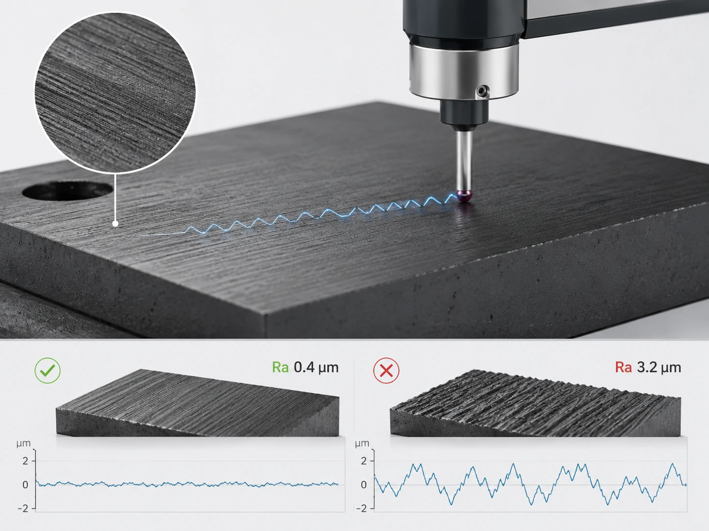
What Ra Actually Specifies on a Graphite Drawing
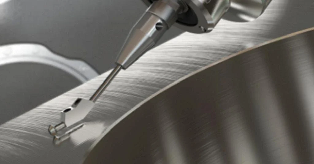
Ra is an arithmetic average roughness parameter derived from a measured surface profile. It summarizes deviations from the mean line over the evaluated length. It does not describe every aspect of surface texture, nor does one Ra value fully describe peaks, valleys, waviness, porosity, tool marks, chipped grains, scratches, or local defects.

That distinction matters in graphite because the material surface is not identical to a homogeneous metal surface. Grain structure, pores, machining marks, chipped particles, and local material pullout can affect a stylus trace or optical measurement. Two surfaces can produce similar Ra values while looking different under magnification, and two nearby traces on the same graphite face can differ if one crosses a pore or local grain feature.
A drawing that specifies Ra should therefore also make clear which surface is controlled. Applying one note such as “Ra X.X all over” can create an unnecessary requirement on faces that have no functional reason to be finished that tightly. The note can also force the supplier to inspect surfaces that were never intended to be measured.
Measurement direction can matter too. A surface milled in one direction may show a different profile when measured parallel or perpendicular to the tool marks. If the requirement is critical, the inspection method should define a repeatable measurement direction and location rather than allowing the operator to choose whichever path produces the best reading.
The correct roughness standard, parameter definition, unit, cutoff, filtering approach, and evaluation length should be confirmed against the current drawing and customer quality system. The supplier should not substitute an informal visual comparison for a contractual surface measurement unless that alternative has been explicitly agreed.
A useful first question during DFM is simple: what functional behavior is the Ra value supposed to protect? If nobody can answer, the requirement deserves review before it is converted into machining time and inspection cost.
Grain Size, Tool Condition, and Process All Influence the Surface
Graphite surface finish is the outcome of several interacting factors. Grain structure influences the scale of the material features exposed by machining, but grain size alone does not determine the final Ra.
Tool geometry and condition are major variables. A sharp tool can leave a different surface from a worn edge. As a tool wears, the effective cutting action changes, which can alter roughness even while the part remains within dimensional tolerance. A finishing strategy that worked on the first component in a batch may produce a different texture later if tool condition is not controlled.
Toolpath also matters. Step-over, engagement, cutting direction, interpolation strategy, entry and exit path, and whether the feature is rough-machined and then finish-machined all affect the resulting texture. The same nominal tool can leave different surfaces on a broad face, a vertical wall, and an internal pocket.
Machine condition and workholding contribute as well. Runout, vibration, tool overhang, spindle condition, part support, and fixture stability can change the surface. A long-reach tool can create a different finish from a shorter, stiffer setup even when nominal cutting parameters are similar.
Dust removal influences inspection. Loose graphite particulate remaining on the surface or stylus path can distort a roughness measurement. The part should be cleaned using the approved method before evaluation, and the cleaning method should not damage a fragile edge beside the measured face.
Because so many variables interact, it is risky to create a universal table stating that a particular graphite grain size always produces a particular Ra. A grade-specific machining trial is more reliable when the surface is important. If the customer has already qualified one material and process, the best production reference is the approved part and controlled drawing rather than a generic roughness chart.
Where Surface Finish Is Function-Critical
Some graphite surfaces genuinely require controlled finish. The need should come from the interface or process.
A sealing face may require a controlled surface because it contacts another sealing component. A sliding or guiding surface may need consistent texture to support motion or contact behavior. An electrical contact face can require controlled geometry and surface condition to support repeatable contact. A thermal interface may also depend on contact condition, although thermal performance cannot be predicted from Ra alone.
Mold and die surfaces can be function-critical when the graphite surface affects release, transferred surface condition, coating behavior, residue buildup, or dimensional stability of the processed part. In these cases, the finish requirement should be connected to the specific workpiece and process rather than borrowed from a different mold application.
Vacuum and high-purity components may care about surface condition for cleaning or contamination reasons, but a low Ra value is not a substitute for a defined cleaning and cleanliness process. Roughness and cleanliness are separate acceptance dimensions. A smooth graphite surface can still carry loose particles or foreign contamination, while a visibly textured surface can be chemically clean.
For each critical surface, the drawing or purchase specification should identify:
- the surface function;
- the roughness parameter and limit if needed;
- the measurement location or zone;
- the measurement direction where relevant;
- the inspection method;
- the relationship to dimensional tolerance and flatness;
- any coating, cleaning, polishing, or post-machining treatment;
- whether chips, scratches, pits, edge damage, or visual defects have separate acceptance criteria.
This makes the requirement traceable to function instead of turning Ra into a decorative quality label.
Where a Tight Ra Adds Cost Without Adding Function
Many graphite parts contain large external faces, clearance surfaces, pockets, reliefs, noncontact walls, hidden areas, and temporary machining surfaces that do not influence performance. Applying the same tight finish to those surfaces adds machining time and inspection burden.
A blanket roughness note can force extra finishing passes. That may require more tool changes, slower machining, more careful handling, additional cleaning, and more measurement. On large parts, inspection time alone can become significant if many surfaces must be checked individually.
Over-specification can also create unnecessary rejection risk. A part may meet every functional requirement but fail because a noncritical surface measures slightly outside a tight Ra limit that was copied from a company drawing template.
The solution is surface classification. Divide the part into critical contact surfaces, functional but noncritical surfaces, and general machined surfaces. Then specify only what each category needs.
This approach improves quotation accuracy. A supplier can price the surfaces that require additional effort rather than assuming the entire part needs premium finishing. It also allows the machining plan to reserve the freshest tool, most stable setup, or dedicated inspection sequence for the surfaces where those controls produce real value.
A useful drawing review asks what changes if the surface is rougher. If the answer is “nothing functional,” the requirement may be a candidate for relaxation. If the answer involves seal behavior, release, electrical contact, optical response, sliding contact, or another defined function, the finish can remain as a controlled characteristic.
The same logic applies in reverse. If the function actually depends on flatness, dimensional fit, or edge condition rather than texture, tightening Ra may not solve the real problem. The drawing should control the characteristic that is causally linked to performance.
Measure Roughness on Graphite Consistently
A roughness value is only useful when the measurement is repeatable. Equipment, probe or optical method, cutoff settings, evaluation length, filtering, measurement direction, surface preparation, support condition, and instrument calibration can all influence the reported result.
Graphite can present local pores or grain features that cause a single trace to differ from another trace nearby. When the surface is critical, the inspection plan may need multiple readings at defined locations rather than one convenient measurement. The acceptance rule should state whether each reading must comply or whether an average is used.
The part should be supported consistently. Flexible or thin graphite sections can move under contact measurement if the support is poor. The measuring force and method should be suitable for the geometry and material.
Cleaning comes before measurement. Loose dust can change readings, but aggressive wiping can damage fragile edges or introduce foreign material. The cleaning method should be part of the inspection procedure where roughness is a contractual item.
Instrument capability also matters. Deep pockets, small bores, narrow grooves, curved surfaces, and faces close to shoulders may be inaccessible to the intended roughness instrument. A requirement that cannot be measured at the actual surface creates a verification problem.
Inspection access should therefore be reviewed during DFM. If a surface must have a controlled Ra, the drawing should allow a realistic measurement method or define an agreed alternative.
Measurement-system consistency becomes especially important when supplier and customer compare results. If they use different probe directions, cutoff settings, instruments, or surface locations, apparently conflicting readings may not represent a true process difference. A shared inspection basis should be established before a dispute occurs.
For repeat production, the supplier can use capability history on the same material, tool strategy, and surface orientation to determine how frequently the surface needs to be checked. That reduces unnecessary inspection while preserving control of the actual risk.
Write Functional Surface-Finish Notes on the Drawing
A good drawing note explains what must be controlled without forcing unnecessary work elsewhere.
Instead of one all-over Ra note, identify the surfaces using labels or symbols. For example, a drawing can define one contact surface as subject to a specific roughness requirement while leaving noncritical faces under the supplier’s normal machined finish.
Where a roughness value is required, use the correct standard notation and unit system. Avoid mixing metric and imperial roughness conventions without clear conversion and review. Do not rely on a translated note that loses the parameter symbol or unit.
If the requirement is tied to a mating part, identify that interface. This helps the machining supplier understand why the surface matters and can guide toolpath and inspection planning.
Surface finish should also be reviewed with edge requirements. A very smooth face next to a fragile sharp graphite edge can create conflicting manufacturing priorities. The drawing may need to define acceptable edge break, chamfer, or corner condition separately.
For repeat production, preserve the drawing revision that was qualified. If a customer later tightens the Ra requirement, treat that as a manufacturing change because it can affect tooling, cycle time, inspection, price, and possibly the recommended graphite grade.
For large parts, consider whether the entire surface must meet the requirement or only a functional band or contact zone. This can materially reduce manufacturing cost while preserving performance.
A functional note can also identify a maximum allowed machining mark direction if direction matters. That is often more informative than tightening the numerical Ra without explaining the interface behavior.
Review Ra Together with Tolerance and Inspection Access
Roughness, dimensional tolerance, and inspection access form one cost system. A tight dimension on a rough surface can be difficult to measure consistently. A tight Ra on a surface that is hard to reach can require specialized inspection. A delicate feature may be damaged by repeated handling for measurement.
During drawing review, ask three questions for every tight surface requirement:
- What function fails if the surface is rougher?
- Can the required finish be machined reliably on this geometry and graphite grade?
- Can it be measured repeatedly with available inspection access?
If any answer is unclear, the requirement should be discussed before production.
This review is particularly useful for deep cavities, narrow grooves, internal bores, curved surfaces, and thin walls. These features may require a different inspection method or a functional acceptance test instead of direct Ra measurement.
A supplier should not silently relax a customer roughness requirement. If the requirement is impractical or appears unnecessary, the correct action is to raise it during DFM and obtain an approved revision or deviation.
The review should also consider tolerance stack. If a surface finish requires extra stock removal after a critical dimension is established, the process sequence needs enough allowance to maintain both requirements. The earlier this is resolved, the lower the risk of late-stage rework.
Functional Surface Review Table
| Surface Type | Typical Question | Specification Approach |
|---|---|---|
| Sealing/contact face | Does interface performance depend on texture? | Define Ra only if function requires it |
| Mold/release face | Does surface affect release or transferred finish? | Tie requirement to process validation |
| Electrical contact | Does contact condition affect resistance/stability? | Control geometry and surface together |
| Thermal interface | Is contact performance sensitive to surface condition? | Avoid assuming Ra alone determines heat transfer |
| Clearance face | Does it contact anything functionally? | Usually no need for premium finish |
| Hidden pocket | Is the surface ever functional or inspected? | Avoid blanket tight Ra if unnecessary |
| Cleaning-sensitive surface | Is cleanliness the real concern? | Separate roughness from cleaning requirement |
| Thin edge-adjacent face | Will finishing threaten edge integrity? | Review Ra together with edge-break requirement |
Common Drawing Mistakes
One very low Ra value applied to the whole part
This increases cost and inspection burden. Classify surfaces by function instead.
Using Ra to control defects such as chips or scratches
Roughness and local defects are different acceptance concepts. Define visual or edge criteria separately where needed.
Specifying a roughness that cannot be measured
Review probe access, orientation, and measurement location before finalizing the drawing.
Assuming finer-grain graphite automatically guarantees the target Ra
Material structure matters, but tooling, tool wear, machine condition, and process also influence finish.
Tightening Ra when the real problem is dimensional fit
Identify whether the functional issue comes from geometry, tolerance, flatness, contact pressure, or actual surface texture.
A numerical disagreement may come from measurement setup rather than from the part. Agree on the inspection basis before treating the readings as nonconforming.
Using Ra as a substitute for cleanliness
A low roughness value does not prove the part is free of machining dust, handling contamination, or residues. Specify cleaning and verification separately where cleanliness matters.
References and Sources
ISO 21920-1:2021 — Geometrical product specifications (GPS) — Surface texture: Profile — Part 1.ISO 230-1:2012 — Test code for machine tools — Part 1.
Related reading: fine-grain graphite and surface finish.