A graphite thread can be dimensionally correct on a CAD model and still be difficult to manufacture, inspect, assemble, or ship without damage. Threads concentrate several risks in one feature: thin crests, roots, runout, interrupted cutting, internal access, dust retention, mating fit, and vulnerable edges.
For that reason, graphite thread machining should be treated as a complete DFM-to-delivery chain. Start with the thread function and mating part, review whether the thread is internal or external, protect the root and crest geometry, choose a machining sequence that reduces chipping, clean the thread before gaging, verify fit using an agreed inspection method, and protect the finished feature during packing and shipment.
Start with Thread Function, Mating Part, and Assembly Method
The first question is why the graphite part needs a thread. The answer determines which characteristics are truly critical.
A thread may retain a component, position an insert, connect to a tube, secure an electrode, hold a furnace fixture, provide an adjustable connection, or simply allow temporary assembly. These functions create different requirements for engagement length, fit, repeated use, assembly torque, contamination, and edge protection.
The mating part should be identified before machining. A graphite internal thread mating with a metal screw behaves differently from two graphite components threading together. Differences in stiffness, thermal expansion, surface condition, and assembly practice can affect the joint.
Assembly frequency is also important. A thread installed once during manufacturing can tolerate a different maintenance strategy from one that is repeatedly assembled and disassembled. Repeated use increases the importance of handling, cleaning, crest damage, and fit verification.
Do not specify tightening torque by copying a metal fastener table. The allowable assembly load depends on the complete joint design, graphite grade, thread geometry, engagement, mating material, temperature, and support around the threaded region. If torque is function-critical, it should come from the engineered assembly and qualification process.
A useful RFQ should identify:
- thread designation and standard;
- internal or external thread;
- mating-part material and thread;
- intended assembly method;
- whether the joint is permanent, occasional, or repeatedly serviced;
- required engagement length;
- surrounding wall thickness and nearby features;
- service temperature and atmosphere where relevant;
- cleanliness or lubrication restrictions;
- inspection and fit evidence required.
This information allows the supplier to review the thread as a functional joint rather than only a machine feature.
Internal vs External Threads Create Different Edge Risks
Internal and external graphite threads expose different sections of material to machining and handling.
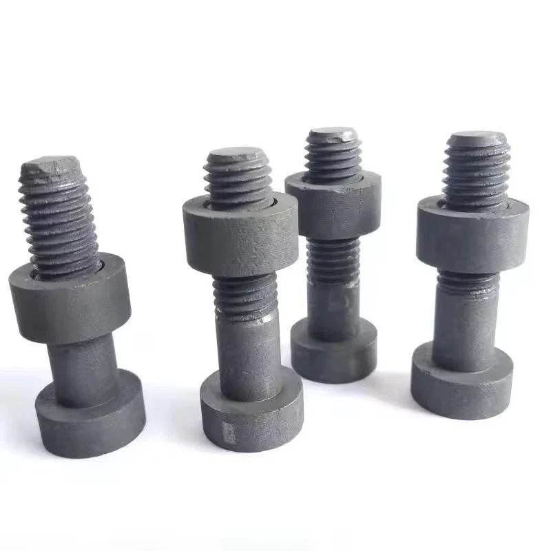
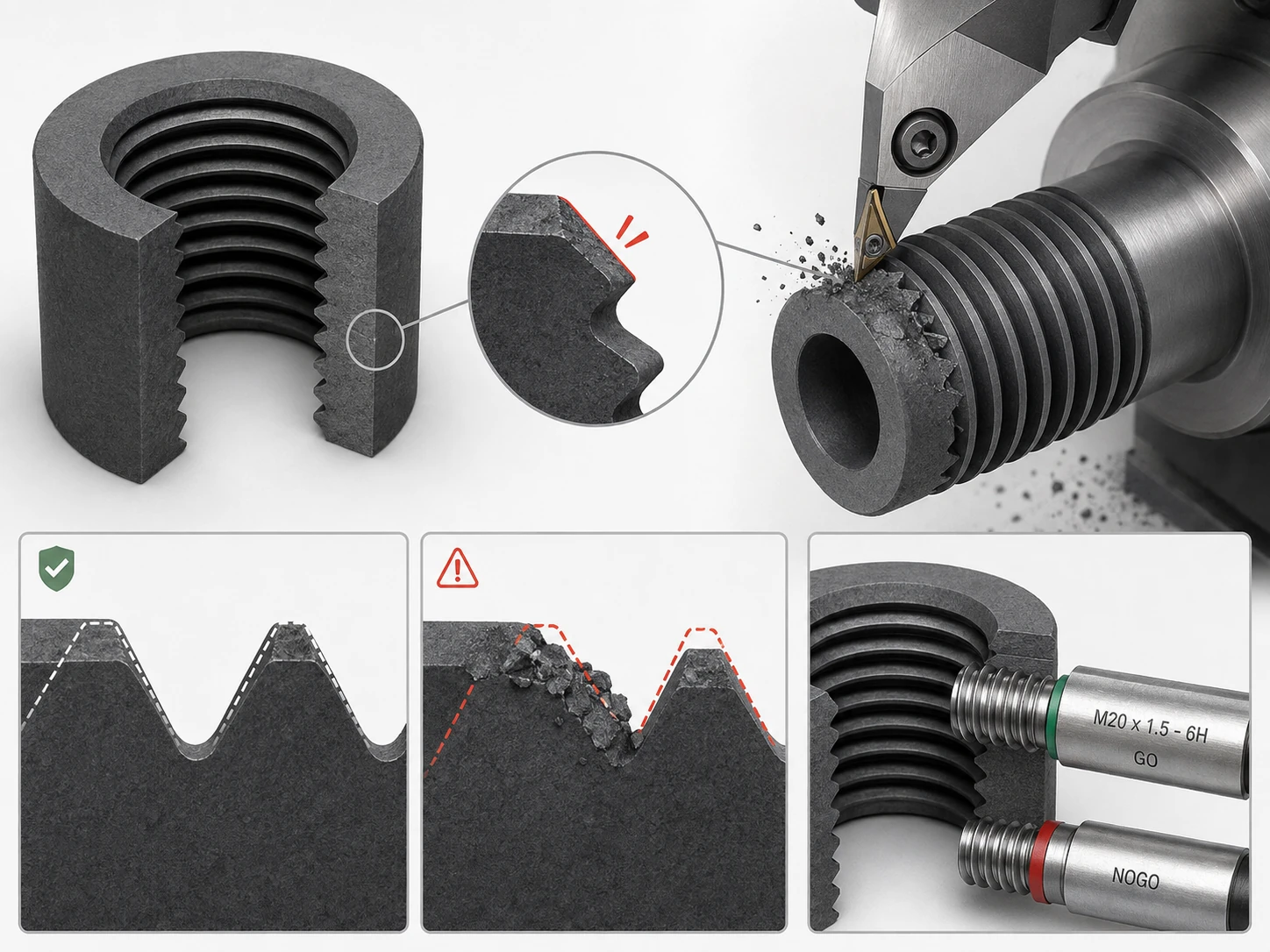
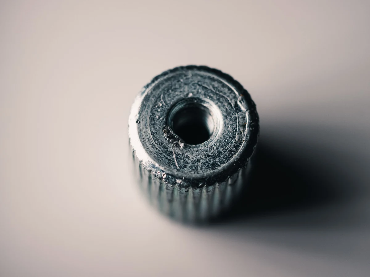
An external thread leaves the crests exposed. Those crests can chip during machining, inspection, assembly, storage, or packaging. The thread start is especially vulnerable because it may contact the mating component first and can be struck during handling.
An internal thread protects the crests inside the bore but creates tool-access and dust-removal challenges. The surrounding wall must be thick enough to support the threaded region, and the entry edge can chip if the tool path or chamfer is poorly planned.
Blind internal threads add bottom clearance and cleaning questions. The usable thread length should be distinguished from the drilled depth and tool runout zone. A CAD model may show thread to the bottom of a hole even though real tooling needs approach and runout space.
Through internal threads simplify chip exit in some cases but create an exit edge that can be damaged during machining or assembly. If the thread intersects another pocket or bore, the intersection should be reviewed for fragile partial teeth.
External threads near the end of a thin graphite tube or neck deserve particular attention. The root removes material from a region that may already be structurally slender. The machining supplier should review the remaining section rather than assume that a standard thread designation is automatically safe in every graphite geometry.
Root, Crest, and Runout Geometry in a Brittle Material
Thread geometry creates repeated stress concentrations. The root is the thinnest local section in many threaded features, while the crest is exposed to chipping. The runout transitions between threaded and unthreaded material and can become a weak zone if the surrounding section is thin.
The correct geometry begins with the applicable thread standard, but the part design still needs DFM review. The designer should avoid unnecessary sharp transitions near the thread and should provide enough surrounding material to support the feature.
Thread starts and chamfers are practical details. A controlled lead-in can reduce the chance that the mating part strikes a fragile full-height first crest. However, the chamfer must not remove so much material that the effective engagement becomes shorter than intended.
Runout should be allowed where the tool needs it. A drawing that demands full-form thread immediately against a shoulder can force difficult tooling or leave an unrealistic inspection requirement. If the shoulder location is function-critical, the customer and supplier should discuss the available manufacturing method before production.
For blind holes, the bottom relief and tool approach should be clear. The usable full thread, partial thread, and nonthreaded bottom zone should not be confused.
Pitch, root geometry, engagement, and surrounding wall section should be set from the actual joint and graphite grade, not from a generic minimum. Capability depends on material grade, part size, wall thickness, mating part, and manufacturing method. The correct limit is established through the actual design review.
Toolpath and Handling to Reduce Chipping
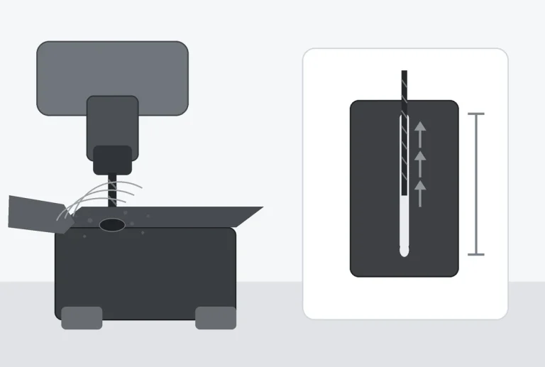
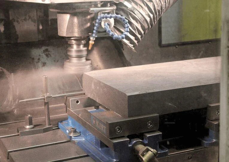
Thread machining can be performed with different tooling and processes depending on size, geometry, access, production volume, and machine capability. The tool choice should support stable cutting and a controllable edge condition.
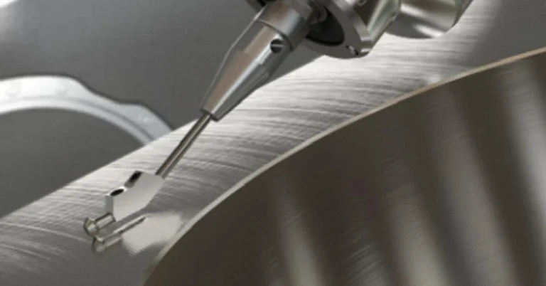
For CNC thread milling, tool reach, interpolation path, entry strategy, and machine accuracy matter. A long-reach tool in a deep internal thread can be less stiff and more sensitive to runout. A shallow external thread may allow a shorter and more robust setup.
Single-point or other threading approaches create different engagement patterns. Select the machining method from thread size, access, engagement length, surrounding section, tool reach, and required inspection evidence.
Tool condition matters because a worn edge can increase local chipping or alter the thread profile. For repeat batches, thread quality should be connected to tool-life records rather than inspected only after assembly problems appear.
Workholding is equally important. A threaded boss or thin tube can be damaged if the part is clamped in a way that distorts or overstresses the surrounding material. The machining sequence should preserve stiffness until the thread is complete where practical.
The thread start and exit deserve special attention. These edges often benefit from a controlled machining order so that the most fragile region is not repeatedly exposed to later roughing, fixture changes, or unnecessary handling.
After machining, operators should avoid using the finished graphite thread as a lifting or holding feature. A thread that passes gaging can still be chipped before packaging if it is treated as a convenient grip point.
Clean the Thread Before Gaging
Graphite machining dust can remain between thread flanks, at the root, in a blind bottom, or around the thread start. Gaging a contaminated thread can produce false resistance, scratch a mating gauge, or make a conforming thread appear tight.
Cleaning should therefore be a defined step before inspection. The method should match the part’s cleanliness requirement and avoid redistributing dust into the room or other features.
For internal threads, inspect the bore visually where access allows and remove retained dust from the full usable length. Blind threads require special attention near the bottom and runout.
For external threads, clean the crests and root without aggressive wiping that could chip fragile edges. If the part is high purity or intended for a sensitive vacuum or furnace process, the cleaning tools and materials should also comply with the customer’s contamination restrictions.
After cleaning, protect the thread from recontamination before final inspection. A freshly cleaned internal thread can collect loose graphite from adjacent machining if other operations continue afterward.
This is one reason process sequence matters: whenever possible, finish and clean critical threads near the point where they can be inspected and protected rather than exposing them to the entire remaining machining route.
Inspection, Fit Checks, and Evidence for Acceptance
A thread is not accepted only because the CNC program used the nominal thread dimensions. The supplier needs evidence that the manufactured feature meets the drawing and fits its intended interface.
Inspection method depends on thread type, size, access, and customer requirement. Thread gauges, mating-part checks, optical or coordinate methods, pitch-diameter measurement, or other techniques may be used where appropriate. The agreed method should be defined before production for critical threads.
Go/no-go style gaging can be useful where standard gauges and the part geometry allow it, but the operator should account for graphite dust and fragile edges. Forcing a gauge is not an acceptable way to make a thread pass.
A mating-part fit check can add functional confidence, especially for custom or nonstandard joints, but it should not silently replace the dimensional or standard acceptance method if the drawing requires one. The mating component used for inspection should also be controlled and identified.
For high-value assemblies, evidence can include the gauge result, inspection date, drawing revision, thread identification, and any customer-defined fit check. This is more useful than a generic statement that “threads checked OK.”
Inspection access should be reviewed in advance. A deep internal thread, small diameter, or thread behind an obstruction may require special equipment. If the customer demands a tight requirement that cannot be measured with the available method, that issue belongs in DFM before the order is released.
Protect Threads During Packing and Shipment
Graphite threads can be damaged after all machining and inspection are complete. Packaging is therefore part of the manufacturing process.
External threads are especially vulnerable to impact. A hard object contacting the crests can create localized chips that were not present at final inspection. Protective sleeves, covers, dedicated cavities, or other noncontaminating packaging features may be appropriate depending on part size and customer requirements.
Internal threads should be protected from debris and impact at the entry. A clean cap or protective insert can help where compatible with the application, but the packaging material should not shed fibers, oils, or particles into a cleanliness-sensitive component.
Parts should not be allowed to contact each other at threaded features during transit. Individual separation is particularly important when the components are heavy enough to damage one another through vibration.
The package should also communicate handling restrictions where necessary. If the thread is not a lifting feature, do not allow the logistics process to treat it as one.
For repeat supply, packaging can be standardized with the part drawing and revision. That prevents the production process from being controlled while the shipping method changes from batch to batch.
Thread DFM Checklist
Before machining a graphite thread, review the following:
- Is the thread function understood?
- Is the mating part identified?
- Is the thread standard and designation complete?
- Is the feature internal or external, blind or through?
- Is surrounding wall thickness adequate for review?
- Does the tool have enough approach and runout space?
- Are the first and last thread edges protected by sensible lead-in geometry?
- Can machining be completed before nearby features reduce support?
- Can the thread be cleaned through its usable length?
- Is the inspection method realistic and agreed?
- Is the thread intended for repeated assembly?
- Are packaging and handling controls defined for the finished feature?
The checklist identifies the conditions that need DFM review before a geometry limit is accepted on the drawing. It exposes the questions that determine whether the specific feature is robust.
Common Failure Modes and What They Suggest
Chipped first crest on an external thread
Check lead-in geometry, toolpath, handling, gaging, mating-part alignment, and packaging. The damage may occur after machining rather than during cutting.
Internal thread feels tight during gaging
Clean the thread first. Then inspect tool wear, effective size, bore condition, runout, and whether the gauge is appropriate for the specified thread.
Crack develops around a threaded boss
Review surrounding wall thickness, assembly load, thread engagement, mating-part alignment, temperature effects, and whether the boss was used for handling.
Thread passes inspection but fails during customer assembly
Compare the customer mating part, inspection method, cleanliness, alignment, assembly process, and whether the correct drawing revision and thread standard were used.
Repeated damage during shipment
The packaging design is part of the root cause. Protect the feature physically instead of relying on a “fragile” label alone.
Threads in High-Temperature and Vacuum Assemblies
Graphite threads used in furnace or vacuum assemblies deserve additional review because temperature and atmosphere can change the joint environment.
The mating parts may expand differently from graphite. Clearance and assembly fit at room temperature should not be assumed to remain identical at process temperature. The equipment or joint designer should account for thermal expansion and service load.
Oxidation can progressively alter exposed thread crests or roots if hot graphite encounters oxygen. A thread with fine features may show functional change earlier than a large solid section. For hot or vacuum assemblies, the process owner should define atmosphere, cooling, mating-material behavior, and the operating temperature range for the complete joint.
Cleanliness also matters. Threads can trap particles or residues, making them harder to clean than open flat surfaces. For critical vacuum use, the cleaning and inspection plan should include the full thread depth.
Lubricants or anti-seize materials should not be introduced without customer approval. A product that is common in metal assembly may be unacceptable for a vacuum, semiconductor, chemical, or high-purity process.
How QDZRT Graphite Reviews Threaded Parts
QDZRT Graphite can review customer drawings for thread access, surrounding material, entry and runout geometry, machining sequence, gaging, cleanliness, and packing risk.
For custom graphite components, the most useful RFQ includes the drawing, thread standard, mating-part information, quantity, graphite grade if already specified, service environment, inspection requirement, and whether the thread will be repeatedly assembled.
If a thread has failed in an existing application, photographs and the damaged component can provide valuable evidence. Identifying whether damage occurs during machining, assembly, service, maintenance, or shipping is more useful than simply increasing the graphite grade or enlarging the thread without analysis.
For repeat production, the approved thread process and packaging should be controlled with the drawing revision. A later change in mating hardware, engagement, geometry, or inspection method can justify re-review.
Thread geometry and the machined graphite surface should be controlled as separate variables. The fine-grain graphite guide covers edge integrity, while the surface-finish guide explains why roughness requirements should be applied only where they serve the thread or mating function.
References and Sources
ISO 965-1:2026 — ISO general purpose metric screw threads — Tolerances — Part 1. Current published tolerance-system reference for ISO general-purpose metric screw threads; it does not define graphite-specific thread strength.ISO 230-1:2012 — Test code for machine tools — Part 1. Machine geometric-accuracy context relevant to process verification, not a material capability guarantee.