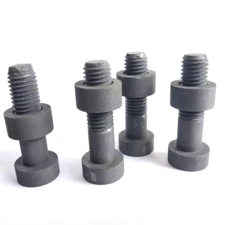
Graphite CNC machining creates fine particulate that can move from the cutting zone into the machine, inspection equipment, surrounding work area, and the finished part. Control the path from generation to collection, machine protection, part cleaning, and final verification rather than treating dust as a housekeeping problem after machining.
This article focuses on process control and machine protection. Site-specific industrial-hygiene, fire, electrical, and environmental design must be handled under the applicable local requirements and equipment documentation. Airflow and filtration have to be engineered for the actual machine, enclosure, dust loading, duct arrangement, and applicable facility requirements.
Control Dust at the Source Before It Spreads
The best place to control graphite dust is at the cutting zone. Once it spreads through the enclosure or room, machine surfaces, measurement areas, and downstream processes all require more cleanup and protection.
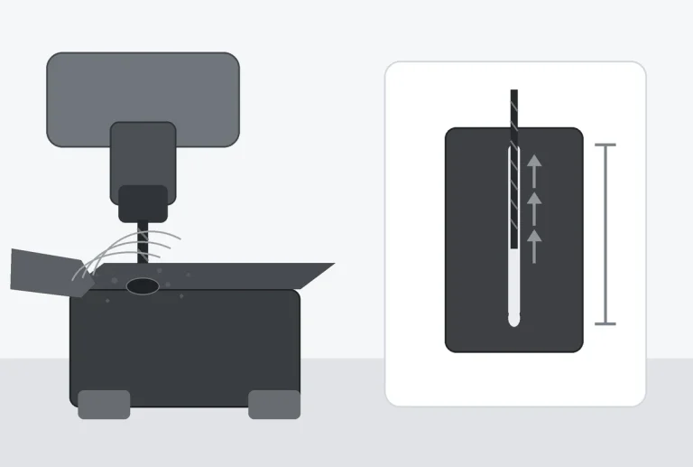
Source control begins by mapping where dust is generated. Milling, drilling, slotting, facing, engraving, and edge finishing can create different dust trajectories. Tool rotation, spindle direction, workpiece orientation, enclosure geometry, and local air movement all affect where particles travel.
The collection inlet should therefore be positioned around the actual cutting plume rather than placed wherever installation is easiest. An inlet that is far from the tool may move a large amount of air while capturing poorly at the source.
Containment also matters. Machine doors, local guards, brush features, shrouds, or other enclosure elements can help prevent particles from escaping before collection. The correct arrangement depends on the machine and tool access; it should not interfere with machining, tool change, workholding, or inspection.
During commissioning, watch representative operations and map where dust accumulates. Correct escape paths and dead zones before simply increasing extraction.
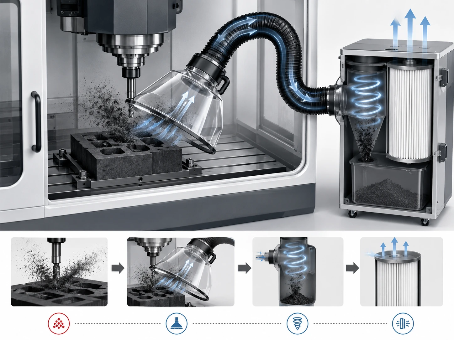
Capture Strategy Around the Cutting Zone
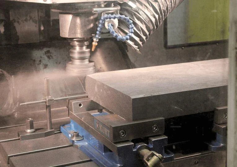
Capture should be designed around the machining process. The collection point needs enough influence at the dust-generation zone to draw particulate away without creating new process problems.
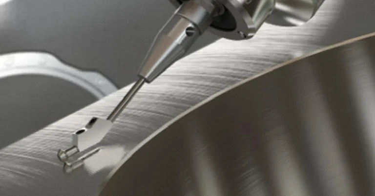
Different machines may use fixed extraction ports, moving nozzles, spindle-adjacent capture, enclosure extraction, or combinations. Each approach has trade-offs. A fixed port is simple but may be less effective when the tool moves far from it. A moving capture point can stay closer to the cut but adds mechanical complexity and collision considerations.
The duct path should be reviewed for accumulation. Long horizontal sections, abrupt changes, unnecessary flexible hose, leaks, and poorly supported runs can reduce system performance or create maintenance problems. The dust collector manufacturer or qualified ventilation designer should define the final system requirements for the actual equipment.
Do not treat airflow as a stand-alone target. Verify that capture remains effective at the tool during representative operations, using pressure or flow data only together with observed containment performance.
When more than one machine connects to a common collection system, simultaneous operation changes the system demand. Branch control, balancing, maintenance condition, and collector loading should therefore be considered at system level.
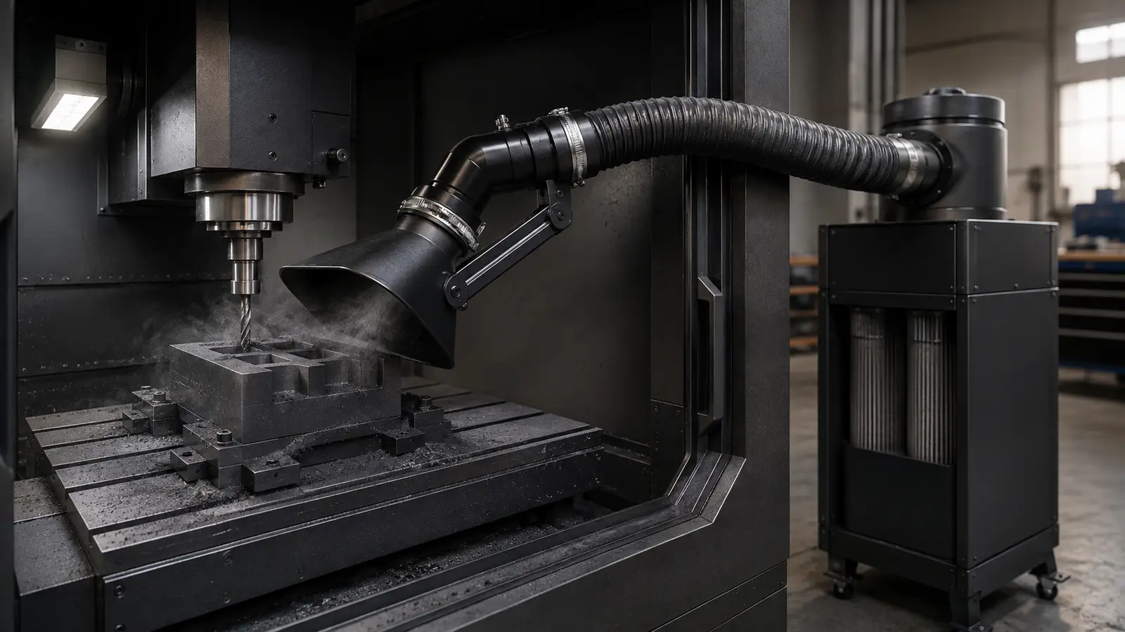
Protect Spindles, Slides, Electronics, and Measurement Areas
Graphite dust is not only a housekeeping issue. Fine particulate can migrate into machine components and surrounding equipment if the machine was not designed or protected for the process.
Spindle interfaces, linear guides, ball screws, seals, tool changers, sensors, fans, cabinets, and measurement devices deserve review. Protection can include machine enclosure, sealing, positive-pressure arrangements where designed by the equipment manufacturer, dedicated covers, local extraction, and disciplined cleaning.
Operators should not improvise modifications that compromise machine cooling, electrical protection, or safety interlocks. Machine-tool manufacturer instructions should remain the controlling source for allowable protective changes.
Measurement areas need separation from heavy dust generation where practical. Granite surfaces, probes, optical systems, precision fixtures, gauges, and reference artifacts can all be affected by particulate. A part measured while dust remains on its datum or measuring surface can produce misleading results even if the machining itself is correct.
Tool storage and presetting areas should also remain controlled. Graphite dust carried on holders or tools can spread outside the machining cell. A defined transfer and cleaning routine reduces this contamination path.
Workholding and Part Cleaning After Machining
A workpiece can leave the machine dimensionally correct but still carry loose graphite dust in holes, slots, threads, recesses, and porous surfaces. Part cleaning is therefore part of the machining process, especially when the component will enter a vacuum, semiconductor, furnace, sealing, or other cleanliness-sensitive application.
Workholding should be designed to minimize inaccessible dust traps where possible. Fixtures that clamp over pockets or enclose lower surfaces can retain particulate. When the part is released, that material can redistribute onto clean faces or measurement datums.
Cleaning method depends on application requirements. Vacuum extraction, controlled gas, brushing, wiping, dedicated cleaning equipment, or other methods may be appropriate, but the cleaning media and tools must themselves be compatible with the customer’s cleanliness needs.
Compressed air should not be treated as a default solution. It can move particulate from the part into the machine or room rather than capture it. Any use of compressed gas should be evaluated within the site’s EHS and contamination-control rules.
After cleaning, inspect areas where dust is most likely to remain: deep holes, blind features, threads, grooves, counterbores, underside pockets, and porous or textured surfaces. The drawing and process plan can identify critical cleanliness zones.
Packaging should preserve the cleaned state. A clean part placed immediately into contaminated foam, paper, or an open shop environment can regain dust before shipment.
Filter Loading, Maintenance, and Housekeeping
A dust-control system changes as it collects material. Filter loading, duct accumulation, leaks, damaged hoses, blocked inlets, and full collection containers can reduce performance over time.
Maintain the collection system according to the equipment guidance and actual shop usage. Filters, seals, ducts, hoses, and collection containers can all reduce capture as their condition changes.
Useful maintenance records include pressure indicators or other manufacturer-specified condition checks, filter-change dates, collector service events, observed capture problems, duct cleaning, damaged seals, and machine-specific dust complaints.
Housekeeping is the secondary control; effective source capture should prevent routine cleaning from becoming the main dust-control method. If floors, cable trays, cabinets, and machine roofs repeatedly collect visible graphite dust, the shop should investigate how the material escapes the process.
Cleaning methods should avoid redistributing fine particulate. Site procedures should follow local occupational-health and combustible-dust requirements as applicable. Graphite machining facilities should not assume that a general office vacuum, household cleaning method, or uncontrolled dry sweeping is suitable for industrial dust.
Waste handling also belongs in the system. Collected graphite dust, used filters, contaminated wipes, and cleaning residues should be managed according to facility procedures and applicable regulations.
Verify Cleanliness Instead of Assuming the Part Is Clean
“Looks clean” may be adequate for some applications and inadequate for others. Cleanliness verification should match the risk of the final use.
For general industrial components, a documented visual inspection under controlled conditions may be sufficient. For sensitive furnace or vacuum parts, the customer may require additional cleaning, particle controls, packaging, or analytical evidence. Those requirements should be defined before quotation because they affect the manufacturing route.
Verification should distinguish machining cleanliness from chemical purity. A high-purity graphite grade can still carry loose machining dust or foreign particles on its surface. Conversely, a visually clean part may not meet an elemental contamination requirement. These are separate acceptance questions.
A practical cleanliness record can include:
- part number and revision;
- machining completion time;
- cleaning method;
- cleaning tools/materials used;
- critical holes or recesses checked;
- visual acceptance result;
- additional customer-required cleanliness test;
- packaging method;
- operator or inspection sign-off.
If customer inspection repeatedly finds dust in one deep bore or recess, add a dedicated cleaning and verification step for that feature instead of increasing general housekeeping everywhere.
Separate Process Guidance from Facility EHS Design
A machining supplier can describe how graphite dust is controlled inside its own process, but that description is not a facility-design specification for another shop. Ventilation, worker exposure, fire protection, electrical classification, waste handling, and collector selection depend on the actual machines, building, jurisdiction, dust loading, occupancy, and equipment configuration.
Facility ventilation should be designed from the actual machine, collector, ducting, dust load, and applicable local requirements. A generic airflow, duct velocity, or filter rating taken from another installation is not a substitute for that design.
For procurement, the useful question is narrower: can the machining supplier demonstrate a controlled path from cutting to cleaning and packaging for the supplied graphite component? That can be reviewed without pretending that the supplier is designing the customer’s entire workshop.
Audit the Dust Path from Tool to Finished Part
A practical audit follows the particulate through the process instead of checking only whether a collector is present. Start at generation: identify which operations produce the largest visible plume or the most hidden accumulation. Then check capture and containment at the actual tool positions used by the program.
Next, inspect the machine-protection path. Determine whether particulate reaches guides, holders, sensors, cabinets, tool-change areas, or measurement surfaces. After machining, follow the part through unloading, cleaning, inspection, and packaging. Blind holes, threads, deep slots, fixture-contact faces, and underside pockets deserve specific attention because they can retain dust after the open surfaces appear clean.
Include maintenance condition in the audit. A system that captures well with new filters can deteriorate as filters load, containers fill, or ducting is damaged; visible accumulation and cleanliness failures are useful warning signs.
| Audit stage | Question | Evidence to retain |
|---|---|---|
| Generation | Where does the operation create particulate? | Representative operation and accumulation observations |
| Capture | Does the collection point influence the real cutting zone? | Commissioning observation or approved equipment checks |
| Containment | Where can dust escape the enclosure? | Leakage or dead-zone observations |
| Machine protection | Are sensitive machine areas remaining controlled? | Inspection and maintenance records |
| Part release | Does unloading release trapped dust? | Fixture and part observations |
| Cleaning | Are internal and difficult features actually clean? | Defined cleaning method and sign-off |
| Packaging | Can the cleaned state be preserved? | Approved packaging method |
Use Cleanliness Feedback as a Process Metric
Customer or incoming-inspection feedback should be recorded by feature and process stage. If particulate repeatedly appears in one blind bore, thread, or packaging area, the corrective action should target that route rather than simply increasing general housekeeping everywhere. This turns cleanliness from a subjective impression into a manufacturing feedback loop.
The same logic applies inside the shop. Repeated dust on one machine roof, cabinet, inspection bench, or aisle can indicate a changed program, declining capture, damaged containment, or a maintenance issue. Recording where the material appears is often more useful than recording only that the collector was running.
What Buyers Should Ask a Graphite Machining Supplier
For cleanliness-sensitive custom graphite parts, the RFQ should identify the critical surfaces, internal features, packaging restrictions, and any required post-machining verification. Buyers can then ask how machining dust is removed, how blind features are checked, how cleaned parts are protected from recontamination, and what inspection evidence can be supplied.
QDZRT Graphite can review those requirements against the customer drawing and intended application. The useful scope is the supplied component: machining, dust removal, cleaning, inspection, and packaging. Site-specific industrial ventilation or safety-system design remains a separate facility engineering responsibility.
The core principle is simple: capture dust where it is generated, preserve cleanliness through inspection and packaging, and use recurring contamination findings to fix the specific weak point in the process.
Link the Control Record to the Part Revision
For repeat production, the control record should identify the exact part revision and the internal features that are most likely to retain particulate. A later drawing revision can add a recess, thread, slot, or covered contact area without changing the graphite grade. That geometry change can alter the work required before the component is ready for inspection and shipment.
For repeat production, link the drawing revision, final inspection, packaging condition, and recurring customer feedback so a cleanliness complaint can be traced to the same geometry and process.
Traceability also helps distinguish a one-time handling event from a repeatable manufacturing pattern. A single damaged or contaminated package points in a different direction from the same internal feature appearing across several production lots. The location and recurrence of the finding should guide the review.
Separate Material Purity from Delivered Part Condition
Material purity and delivered part condition answer different questions. A high-purity graphite grade can still carry loose graphite particulate or foreign material after machining and handling. A component that appears visually acceptable can also require separate material evidence when the application has elemental or contamination limits.
The RFQ and inspection plan should therefore keep those acceptance dimensions separate. Material certificates support the specified graphite identity and chemistry. The finished-part record supports the condition of the component after machining, inspection, and packaging. One should not be used as a substitute for the other.
This distinction also improves supplier communication. When a customer reports an issue, identify whether the concern is retained graphite, foreign particulate, material chemistry, package condition, or another defined finding. A specific description supports a more useful corrective review than the broad statement that the part is unacceptable.
Dust control is connected to the machining route but should not be reduced to a tooling preference. The diamond-coated versus carbide tooling guide covers tool-life decisions separately; this article keeps the focus on containment, housekeeping, machine protection, and cleanliness verification.
References and Sources
- NIOSH Pocket Guide — Graphite (natural). Occupational-hazard and measurement-method reference for natural graphite.
- NIOSH Pocket Guide — Graphite (synthetic). Separate occupational-hazard entry for synthetic graphite, reinforcing that exposure controls should follow the actual material and applicable workplace rules.