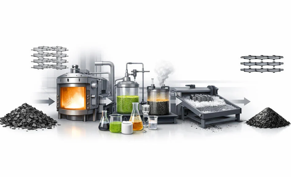
Graphite purification converts a mineral concentrate or synthetic-carbon feed into a grade whose ash and trace impurities fit the next industrial process. The target is not merely a higher carbon percentage. Conductivity, corrosion behaviour, thermal stability, battery performance, semiconductor cleanliness and high-temperature contamination can each be controlled by a different impurity.
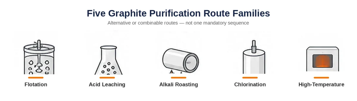
QDZRT Graphite supplies natural flake graphite and purified graphite products within the documented scope of each quotation and specification. The main route families remain flotation, mineral-acid or hydrofluoric-acid leaching, alkali roasting followed by leaching, chlorination and high-temperature treatment. A buyer, processor and supplier should select or combine those routes from the feed mineralogy, particle form, residue limits, process restrictions, inspection method and approved acceptance plan; no single route optimises recovery, flake preservation, purity, safety, environmental burden and delivered cost for every grade.
Why Purity Is Not One Number
A certificate that states “99.9% carbon” leaves an arithmetic difference of 0.1%, or 1000 ppm, from 100%. That calculation is useful only as a theoretical balance: it is not by itself the ash value, the mineral content or the sum of iron, silicon, sodium, sulphur and other trace elements. Fixed carbon by difference, elemental carbon, ash and an element-by-element impurity panel answer different questions and must not be substituted for one another.
Natural graphite ore contains quartz, mica, feldspar, clay, carbonates, iron-bearing minerals and other gangue. Liberation and flotation remove much of the physical gangue. Chemical treatment dissolves or converts selected minerals. Thermal treatment volatilises impurities whose vapour behaviour differs from graphite. Each route therefore attacks a different impurity group.
Particle size and flake structure must survive the purification route when the application values them. Aggressive grinding can lift carbon recovery but destroy +50 mesh flake. Strong chemical treatment can remove ash while changing surface chemistry. A 99.95% fine powder is not an upgrade from a 95% coarse flake when expansion volume or large-flake morphology is the required property.
The test method changes the reported result. Fixed carbon may be calculated from moisture, volatile matter and ash under an agreed procedure, while elemental carbon is measured by a separate combustion method. ASTM C561-23 describes ash as a practical estimate of nonburnable residue for comparing commercial graphite grades, but it also states that the relationship between ash and mineral content is unknown and that the method is not intended for some purified graphites such as nuclear materials. ICP-OES, ICP-MS, GDMS or another validated elemental method then quantifies selected elements under its own digestion, calibration and detection limits. Every specification therefore needs the reported metric, test method, unit and release limit on the same line.
| Reported metric | Method or calculation basis | Unit | What the result answers | What it does not establish | Additional project controls |
|---|---|---|---|---|---|
| Fixed carbon by difference | Approved proximate-analysis or loss-on-ignition calculation stated in the order | wt% | A calculated carbon-related balance under the stated moisture, volatile and ash procedure. | Does not identify individual elements; the mathematical difference from 100% is not by itself ash. | Moisture basis, volatile-matter basis, ash method and rounding rule. |
| Elemental carbon | Validated combustion or instrumental method stated by the laboratory | wt% | Carbon measured directly under the selected analytical procedure. | Does not describe mineral species, soluble residues or each metallic impurity. | Calibration, sample preparation, reporting basis and measurement uncertainty. |
| Ash | ASTM C561-23 where suitable, or another approved ash method | wt% | A practical estimate of nonburnable residue under the stated combustion conditions. | Does not determine mineral composition and may be unsuitable for some purified-graphite applications. | Sample mass, furnace conditions, blank correction and method suitability. |
| Individual elements | ICP-OES, ICP-MS, GDMS, PIXE or another validated element method | ppm or mg/kg | The concentration of listed elements such as Fe, Si, Al, Na, Ca, B or Ti. | A short element list does not establish all possible impurities; results depend on preparation and detection limits. | Required elements, digestion or direct-solid method, detection limit and retest rule. |
| Moisture and volatile matter | Approved drying and volatile-matter methods | wt% | Handling condition and volatile loss on the agreed reporting basis. | Does not replace fixed carbon, ash or trace-element analysis. | As-received or dry basis, sample conditioning and packaging condition. |
Purity is incomplete without an impurity profile and a method statement. The U.S. Geological Survey maintains public graphite statistics and information covering supply, demand and material flow, while the product specification must go further by identifying the impurities that control the actual end use.
Flotation: The First Beneficiation Step
Flotation uses graphite’s natural hydrophobicity. After crushing and staged grinding, air bubbles carry graphite-rich particles into the froth while much of the wetted gangue remains in the slurry. Regrinding and cleaner flotation repeat the separation until the concentrate reaches the grade and recovery balance.
Flotation performance must be reported against the actual ore and size distribution. It is commonly used to upgrade low-grade ore to a concentrate suitable for sale or further purification, but feed grade, liberation, reagent scheme and cleaner stages differ by deposit. A statement such as “80–95% fixed carbon” is therefore a screening description rather than a release range; the certificate should report the measured product grade, carbon recovery, mass recovery and retained size fractions for the specific campaign.
Flotation is generally the lowest-burden separation stage because it handles large throughput without the reagent, wastewater or furnace load of later purification. That qualitative position does not justify a universal cost index. Power, grinding intensity, water treatment, reagent consumption, tailings handling and recovery of valuable coarse flakes must be evaluated for the actual plant and feed.
Flake preservation is the process constraint. Grinding must liberate silicates without turning valuable +50 or +80 mesh flakes into -100 mesh material. Staged grinding removes liberated coarse concentrate before the remaining stream receives more energy. The natural flake graphite guide explains how particle class and fixed carbon work together.
Recovery and grade move against each other during the cleaner stages. A plant can reject more middlings and report a cleaner concentrate, yet lose coarse graphite that carries most of the product value. The relevant calculation therefore separates carbon recovery from mass recovery and tracks each size fraction. If +50 mesh represents 20% of the feed value, losing half of that fraction cannot be hidden by a higher average carbon result in the fine product. This is why a flotation certificate for commercial flake should report fixed carbon by size class, retained percentage on each sieve and total recovery, giving more detail than a single blended purity number. The route earns its low cost only when it preserves the material the next process actually needs. Cheap separation can still destroy expensive flake when the grade improvement is achieved by losing the size fraction that carries the product value.
Flotation leaves embedded fine silicates, intergrown minerals and trace compounds that cannot be separated by surface wettability alone. Those residues decide whether the next step is acid leaching, alkali roasting, high-temperature purification or no further treatment. For refractory, friction, lubricant or expandable graphite feed, preserving flake can be worth more than chasing another purity point.
Acid Leaching
Acid leaching dissolves impurities that react with the selected acid while graphite remains as the solid phase. Hydrochloric, sulphuric or nitric acid can remove carbonates, iron compounds and other acid-soluble minerals. The result depends on mineralogy, acid concentration, temperature, particle size, mixing and washing.
Mineral-Acid Leaching
Mineral-acid leaching can remove carbonates, iron compounds and other acid-soluble phases, but the final carbon result depends on the concentrate mineralogy, acid system, temperature, particle size, mixing, filtration and washing. Quartz and some aluminosilicates resist ordinary mineral acids, so a single reported carbon range cannot be transferred between deposits or used as a guaranteed route capability.
The process creates dissolved metal salts and an acidic wash stream. Incomplete washing leaves chloride, sulphate or nitrate on the graphite surface. Drying can concentrate those ions. A final conductivity or ion test on wash water can therefore be as important as the carbon result.
Hydrofluoric-Acid Purification
Hydrofluoric acid attacks silicon-bearing minerals that resist ordinary mineral acids and may be selected when silicate removal is the controlling objective. Product purity and recovery must still be reported as results from the specific feed, acid concentration, temperature, time, solid-to-liquid ratio and washing sequence; an HF route name alone does not establish a 99.5% or 99.95% outcome.
Its limitation is not chemistry alone. HF is highly toxic and strongly corrosive. The NIOSH Pocket Guide entry for hydrogen fluoride lists a 3 ppm time-weighted recommended exposure limit, a 6 ppm 15-minute ceiling and a 30 ppm IDLH value. Those figures provide occupational-hygiene and emergency context; they do not design the reactor, ventilation, materials of construction, fluoride-waste system or emergency response. Those controls require local law, permitting, an engineering hazard analysis and site-specific equipment design.
Calcium, magnesium, iron and aluminium can form secondary fluorides or complexes. Additional hydrochloric or nitric treatment may be used to remove them. That is why “HF purified” does not guarantee low fluoride residue. Final washing, neutralisation and element testing remain necessary.
Washing must be built into the purification process itself, planned and executed alongside the reaction rather than treated as an afterthought. The graphite cake traps liquor between particles, and finer powder retains more solution per kilogram than coarse flake. One wash can reduce free acid while leaving soluble salts inside the filter cake. Repeated displacement washing, conductivity tracking and selected-ion analysis establish the endpoint. Drying temperature then matters because residual liquor becomes more concentrated as water leaves. A lot can meet fixed-carbon and ash limits yet fail a chloride or fluoride limit after drying. Where the application controls corrosion or electrochemical stability, the release certificate needs the residue result from the dried product rather than a measurement taken only from the final wash water. The last wash does not by itself prove the dried powder, because retained liquor and salts can concentrate during drying.
Acid treatment can be considered for high-purity graphite powder, conductive formulations and intermediate material that will receive another purification step. The feed mineral analysis, final particle form, permitted reagents and dried-product residue limits must determine the exact route.
Alkali Roasting
Alkali roasting, also called alkali fusion in some routes, converts resistant silicates and aluminosilicates into compounds that can be leached. Graphite concentrate is mixed with sodium or potassium alkali and heated, followed by water washing and acid leaching. The chemical sequence removes silicon-containing gangue that ordinary acid cannot dissolve efficiently.
Alkali roasting conditions must be treated as feed-specific test results rather than an industry-wide 400–800 °C or 99.0–99.9% rule. A published pilot-scale example used a concentrate containing 85.6% carbon, upgraded it by flotation, then roasted the concentrate at 500 °C for 90 min before acid leaching to produce a reported 99.82% carbon product. The study offers one route example only, without a transferable guarantee for other mineralogy, particle size, reagent ratio or equipment.
The method proceeds through a sequence of steps rather than occurring in a single reactor. Alkali dosage must be sufficient to react with the gangue but not so excessive that washing cost and sodium residue rise. The roasted mass needs controlled cooling and dissolution. Acid leaching then removes converted metal compounds. Multiple wash stages reduce soluble salts.
Residue shifts as the process moves. Quartz and aluminosilicate decline; sodium, potassium, chloride or sulphate can become the new concern. A carbon result of 99.9% does not show whether sodium is 20 ppm or 500 ppm. Battery and electronic applications need the element result.
The reagent ratio is tied to mineral mass, not graphite mass. Two concentrates at 95% carbon can need different alkali additions when one contains quartz and the other contains clay or feldspar. Excess alkali increases conversion but also raises salt load, wash-water demand and the risk of sodium remaining on the product. Insufficient alkali leaves an unreacted silicate core that appears in the final ash. A useful development test records feed mineralogy, alkali-to-ash ratio, roast temperature, hold time, washed yield and sodium after drying. Those results reveal whether the route has reached a chemical limit or merely needs better contact and washing.
Alkali roasting may fit natural concentrates with persistent silicate or aluminosilicate ash. It can feed natural graphite powder, micronized graphite powder or further shaping and purification, but the project comparison must include alkali consumption, roasting energy, acid demand, dissolved-salt load, wash-water volume, corrosion and sodium or potassium remaining after drying. The route cannot be ranked as environmentally preferable to HF without a project-level material and energy balance.
High-Temperature Purification
High-temperature purification heats graphite in vacuum or a controlled oxygen-free atmosphere so selected impurities volatilise while graphite remains. A recent natural-flake study used a fixed-bed furnace at 2500 or 2800 °C for 15–120 min and a separate counterflow reactor averaging about 2700 °C. The published study showed that temperature, hold time and flake-size fraction materially changed the result: 2800 °C fixed-bed tests reached above 99.99 wt% carbon after 15 min for the tested material, while medium flakes at 2500 °C remained lower even after longer treatment. Those values describe the named feed, reactors and analytical methods and cannot be generalised into a universal 2500–2800 °C product specification.
High-temperature treatment avoids the same large aqueous leach stream produced by some chemical routes, but it transfers burden to electricity, inert gas or vacuum, furnace insulation, hot-zone maintenance, emissions management and cycle time. Chemical pre-cleaning may reduce furnace load, while an unsuitable feed may consume expensive hot-zone capacity. Environmental comparison therefore needs energy source, furnace utilisation, aqueous-waste treatment, off-gas control, reagent recovery, equipment life and local disposal data rather than a single “cleaner route” label.
Temperature is not the only control. Vacuum level, inert-gas purity, residence time, bed depth and impurity vapour pressure determine removal. Some elements are difficult to volatilise in their existing form. Reactive-gas treatment can convert them into more volatile compounds, but that changes safety and corrosion requirements.
Furnace loading changes the result. A shallow bed shortens the impurity-vapour path but uses less hot volume; a deep bed improves charge utilisation while increasing the risk of uneven heating or recondensation. Container graphite, insulation and gas lines can introduce elements not present in the feed. The cited natural-flake study also found that Fe and Si results could differ by more than one order of magnitude among analytical techniques. Release therefore requires a method-specific detection limit, a defined lot and a sampling plan justified by demonstrated furnace uniformity rather than a fixed instruction to take exactly three top, middle and bottom samples. Peak temperature is only one coordinate alongside time, size fraction, reactor design, atmosphere, load geometry and analytical method.
Chlorination Roasting
Chlorination roasting converts selected metal or mineral impurities into volatile or removable chlorides under heat and a controlled gas system. The achievable purity depends on feed chemistry, gas composition, temperature, residence time, reactor materials, off-gas capture and subsequent dechlorination or washing. It should be evaluated as a specialised project route rather than assigned a general 99.5–99.99% output range.
Chlorine toxicity, corrosion and off-gas control limit routine adoption. The NIOSH Pocket Guide entry for chlorine lists a 10 ppm IDLH value and a 0.5 ppm 15-minute recommended ceiling. These are occupational-hygiene and emergency values only. Reactor containment, scrubber duty, construction materials, leak detection, emergency isolation and permitting must come from an engineering hazard analysis and applicable regulations.
High-temperature or chlorination routes may be considered for selected semiconductor, nuclear, aerospace, advanced thermal and battery-grade graphite anode materials, but each application controls different elements and detection limits. The linked OSTI publication is retained only as a coal-derived graphite case: it uses sub-bituminous coal, Fe₂O₃-catalysed graphitisation, HCl recovery and a KOH rinse to produce low-ash graphite. It is not evidence for the standard purification of natural flake graphite and should not be used to generalise natural-graphite furnace conditions.
Comparing Process Burden and Delivered Cost
Purification cost is nonlinear and cannot be reduced to a universal cost-per-purity-point index. Removing bulk gangue by flotation and removing the final trace contaminants require different equipment, analysis and contamination control. The economic comparison must use the same feed, final particle size, residue specification, yield definition, certificate scope and packaging standard.
Cost also depends on yield. A chemical route can achieve high purity while losing fine graphite during filtration and washing. Thermal treatment can preserve carbon mass but consume more energy. Large-flake value can fall if the material is ground to expose impurities. A quotation therefore needs product yield, not only process cost.
| Route | Main separation mechanism | Impurities or constraints to characterise | Required project inputs | Direct evidence or example boundary | Process-burden variables |
|---|---|---|---|---|---|
| Flotation | Physical separation based on liberation and surface behaviour | Gangue mineralogy, intergrowth, flake size and liberation | Ore grade, size distribution, reagent scheme, cleaner stages and recovery by size fraction | Report the actual campaign grade and carbon/mass recovery; do not transfer one deposit’s range to another. | Grinding power, water, reagents, tailings and loss of valuable coarse flake. |
| Mineral-acid leaching | Dissolution of acid-soluble mineral phases | Carbonates, iron compounds, resistant silica and soluble anion residues | Acid system, concentration, temperature, time, solids ratio, filtration and dried-product wash endpoint | A route name does not guarantee a fixed product-carbon or recovery range. | Acid use, filtration, neutralisation, wastewater, corrosion and drying. |
| HF leaching | Attack on silicon-bearing phases | Silicate load, secondary fluorides and fluoride residue | Feed mineralogy, HF concentration, contact conditions, construction materials and fluoride limits | Use lot-specific results plus NIOSH data only as occupational-hygiene context. | Containment, ventilation, emergency systems, fluoride waste and corrosion-resistant equipment. |
| Alkali roasting plus acid | Conversion of silicates followed by dissolution and leaching | Quartz, aluminosilicates, Na/K residue and dissolved salts | Alkali-to-ash ratio, roast conditions, wash sequence, acid demand and sodium/potassium release limits | One pilot study reported 85.6% carbon in the feed, 500 °C for 90 min and a 99.82% product under its stated conditions. | Roasting energy, alkali/acid consumption, salt wastewater, washing and corrosion. |
| Chlorination | Conversion to volatile or removable chlorides | Gas-reactive impurities, chloride residue and reactor corrosion products | Gas chemistry, temperature, time, reactor materials, scrubber and dechlorination plan | Specialised project route; purity and recovery require feed- and reactor-specific evidence. | Gas supply, containment, off-gas treatment, maintenance, permitting and emergency controls. |
| High-temperature | Volatilisation in vacuum or controlled non-oxidising atmosphere | Particle-size effect, low-volatility elements and furnace pickup | Feed purity, size fraction, temperature/time profile, atmosphere, load geometry and analytical method | Natural-flake research at 2500/2800 °C showed materially different results by size, time and method. | Electricity, furnace utilisation, inert gas/vacuum, hot-zone life, cycle time and clean handling. |
Cost per delivered kilogram includes the reaction and everything needed to release the lot. Acid routes add filtration, neutralisation, wastewater treatment and corrosion-resistant maintenance. Alkali routes add roasting energy and a dissolved-salt stream. Chlorination adds containment and off-gas treatment. Thermal routes concentrate spending in electricity, furnace depreciation, inert gas or vacuum and cycle time. Analytical cost rises as the specification moves from total ash to a low-ppm element panel. Packaging must then preserve the purity already purchased; a clean powder loaded into a contaminated liner has lost value without changing process yield. The cheapest reactor does not guarantee the lowest cost of a conforming delivered product.
A comparison should list feed mass and grade, saleable product yield, element-specific release limits, energy and reagent use, waste streams, analytical plan, packaging and logistics. A 2026 comparative natural-graphite study of sulfuric-acid leaching, thermal treatment and combined routes shows why route burden must be reported by measured conditions rather than a general ranking; the study reports different removal behaviour for iron, aluminium and silicon and identifies distinct chemical and thermal burdens. Local energy, reagent recovery, wastewater treatment and feed mineralogy can reverse the apparent order between routes.
Which Method Leaves Which Residue
Every purification route leaves a different residue and control signature. Flotation can leave locked or fine mineral matter. Mineral acids can leave resistant silica and soluble anions when washing is incomplete. HF can leave fluoride species or secondary fluorides. Alkali roasting can leave sodium, potassium and soluble silicates. Chlorination can leave chlorides and corrosion products. High-temperature treatment can leave low-volatility elements or introduce furnace pickup. The release plan must convert those risks into project-specific limits and methods rather than copying fixed ppm, conductivity or sample-count examples.
| Method | Main residue risk | Project limit to define | Analytical or process check | Sampling and lot definition | Release and retest rule |
|---|---|---|---|---|---|
| Flotation | Locked Si-, Al- or Fe-bearing minerals and size-fraction variation | Ash, mineralogy or listed elements by product size class | Approved ash/mineralogy/element method with detection limits | Define concentrate lot and size-fraction composite plan | Release measured grade and recovery by the approved plan; specify retest of nonconforming fractions. |
| Mineral acids | Resistant silica and residual chloride, sulphate or nitrate | List each controlled anion or element and its reason | Dried-product ion/element analysis plus documented wash check | Define batch, increments, drying condition and composite method | Final dried-product result controls; wash-water result alone is not release evidence. |
| HF | Fluoride, CaF₂/MgF₂ and residual metals | Fluoride and selected metal limits tied to application | Validated fluoride and element methods on dried product | Define chemical batch and representative packed-lot sample | State confirmation, retest and disposition rules for fluoride or metal failure. |
| Alkali roasting | Na, K, soluble silicates and acid-derived ions | Na/K and other application-specific limits | Element panel and approved wash endpoint with method | Define roast/leach batch and any segregation by vessel or drying lot | Release by the approved dried-product limits; investigate process carryover before blending or retest. |
| Chlorination | Chloride and reactor-corrosion metals | Chloride plus listed construction-metal limits | Product analysis, off-gas record and dechlorination verification | Define reactor charge, location risk and clean-transfer boundary | Release under the approved gas-process and product-test plan; set repeat-test and disposal criteria. |
| High-temperature | Low-volatility B/Ti/V or furnace/container pickup | Element-by-element limits with method detection limits | Approved direct-solid or digestion method plus furnace condition record | Base locations and increment count on demonstrated charge uniformity | Release the defined furnace lot; investigate location bias and method disagreement before retest. |
Residue limits need an engineering reason. Iron may matter for corrosion, magnetic cleanliness or electrochemistry; sodium and potassium can affect ionic contamination; silicon may dominate ash without producing the same failure as soluble chloride; and boron can be critical in selected nuclear or semiconductor uses even when total ash is low. The specification should list the elements or ions linked to failure, the analytical method and the detection limit, while using total ash only as a supporting control. A broad element panel at the laboratory’s lowest possible detection limit is justified only when the application and risk analysis require it. A residue limit needs a defined engineering consequence, or it becomes an expensive number without a release function.
Testing must follow the end use and the approved inspection plan. Our conductive and functional materials, battery and energy-storage materials and high-temperature processing pages show why different applications focus on different residues, product forms and qualification evidence.
Specifying Purity on the Order
The order identifies the starting and finished product forms: natural flake, natural powder, shaped material or synthetic graphite powder. Our specification review records particle-size distribution, the moisture reporting basis, the fixed-carbon or elemental-carbon test method, the ash test method, and the acceptance limits for individual elements or ions used to approve the production lot.
Write limits with units and methods. A phrase such as “high purity” is not testable. A project specification may list a fixed-carbon or elemental-carbon minimum, ash maximum, selected Fe/Si/Na/B or other element limits, moisture and particle-size distribution, but the actual values must come from the application and approved test plan. The document must also state whether results are reported as received, dry basis or another controlled basis.
Sampling needs a lot definition. A shipment assembled from several production batches may require separate certificates or a validated composite plan. State the production-lot boundary, increment locations, composite method, retained-sample mass, sample container, laboratory split and retest rule. The number of samples must follow lot size, segregation risk, process uniformity and the approved inspection plan rather than a fixed one-, two- or three-sample convention. Packaging must prevent moisture pickup and cross-contamination after purification.
Do not specify a purification method unless the route itself matters. An application may require a fluoride-free process, a chlorine-free process or thermal treatment because of residue restrictions. In other cases, the buyer, processor and supplier should jointly confirm the route from feed analysis, product-form requirements, residue limits, process restrictions and the approved specification. The graphite export documentation guide explains the connection between material identity, certificate and shipment.
Future routes such as hydrothermal treatment, plasma purification and combined flotation-chemical-thermal sequences remain relevant. They should be evaluated by the same outputs: purity, yield, residue, energy, wastewater, scale and repeatability. A new process name does not replace a lot certificate.
Send QDZRT Graphite the feed description, target reporting basis, impurity and residue limits, particle-size distribution, moisture limit, application and annual quantity through the contact page. The technical review can then define which supply form and purification route should be evaluated, what evidence is required from the processor and which measurements will control quotation and lot release. Final route selection remains subject to documented process capability and the approved order specification.