Natural flake graphite does not leave the mine as a finished industrial grade. The ore contains graphite crystals mixed with silicates, carbonates, sulphides, clay and moisture. Processing removes part of that mineral burden, protects or breaks the flakes, separates particle sizes and raises fixed carbon to the level required by the next operation. Each step changes a different part of the specification.
QDZRT Graphite supplies natural flake graphite and related raw-material grades for industrial processing. The sequence below follows the material from run-of-mine ore to screened, purified or expandable product. The numerical entries are illustrative process checkpoints rather than industry-wide specifications. A purchase order should define the fixed-carbon basis and method, particle-size method, moisture method, sampling plan and any density test. The term “available carbon” should not be used as a separate purchase requirement unless the supplier and buyer define its test basis; fixed carbon should instead be stated with an agreed test method.
What Comes Out of the Ground
Ore grade sets the amount of work that follows.
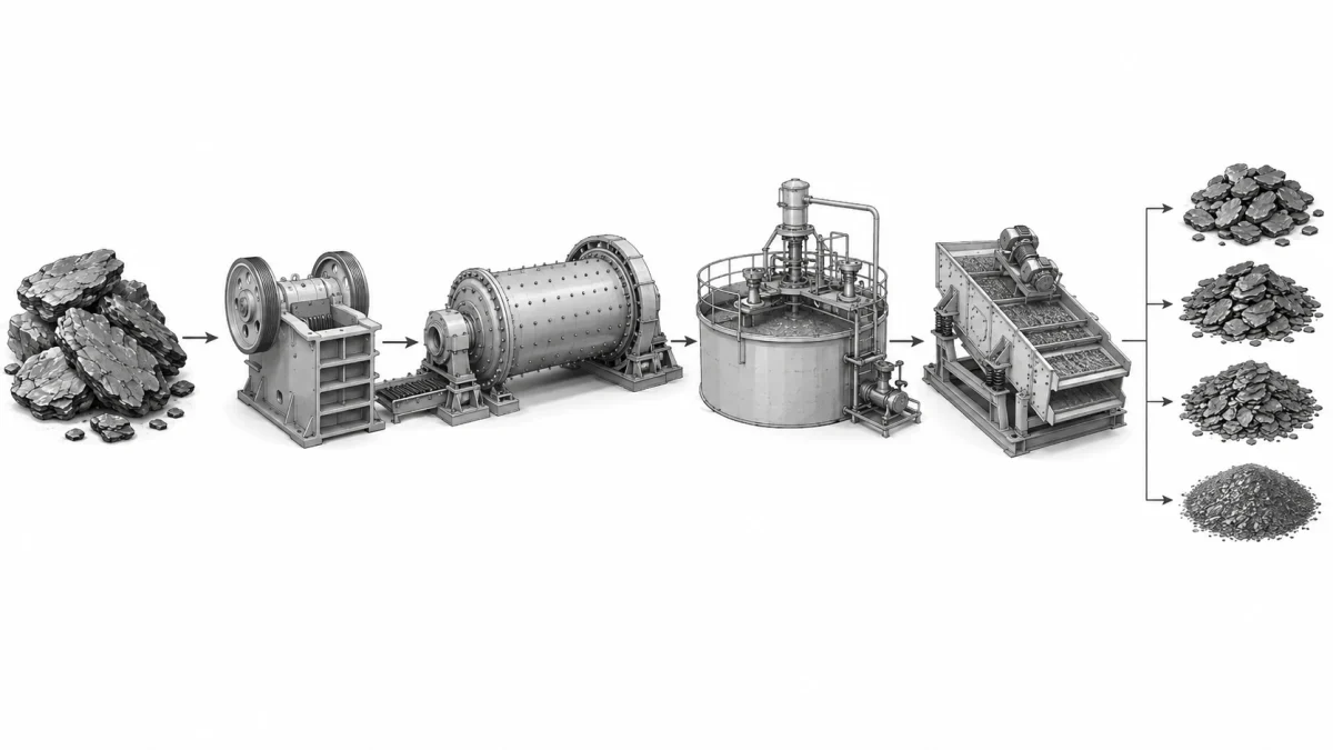
A graphite deposit contains flakes distributed through host rock. Mining delivers pieces of ore, not free flakes. Crushing and grinding open the rock so flotation reagents can contact the graphite surface. Too little liberation leaves graphite locked to gangue; too much grinding turns large flakes into smaller particles and lowers the value of a coarse-flake product.
The first specification is therefore mineralogical, set before any commercial grade applies. Feed carbon, flake occurrence, gangue type and liberation size determine the flowsheet. An ore with 8% graphitic carbon and coarse liberated flakes behaves differently from a 20% feed whose graphite is finely intergrown with mica. The final fixed-carbon number alone does not show how much yield or flake size was lost to reach it.
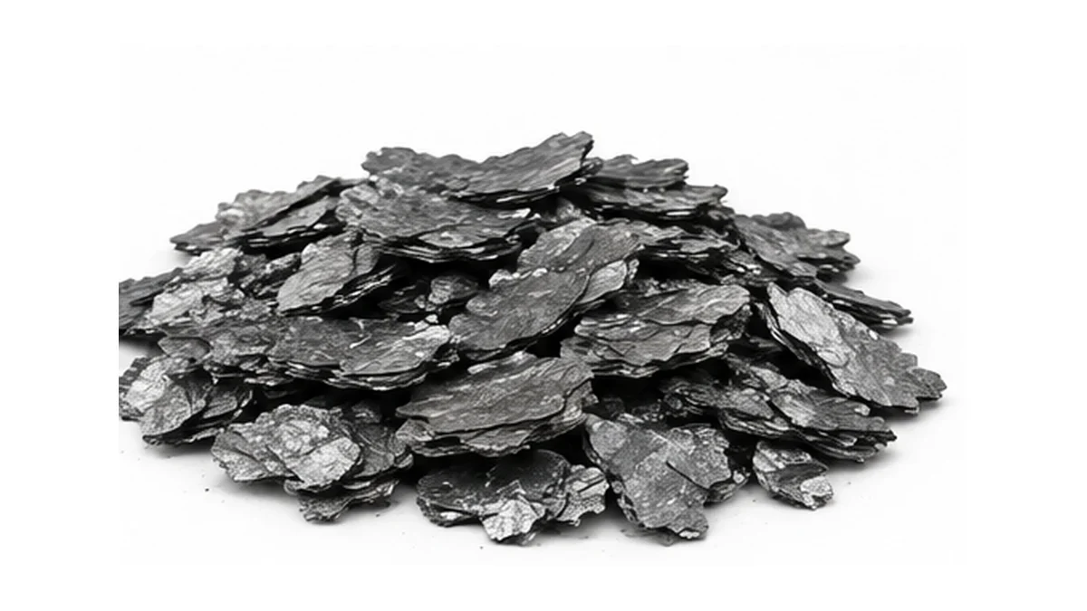
Natural flake morphology matters because plate-like particles give the material lubricity, thermal stability and directional conductivity. Those features support refractory mixes, friction products, conductive coatings, sealing feedstock and downstream expansion. The same lamellar structure also makes the flakes susceptible to mechanical breakage during milling.
| Stage | Feed or product state | Fixed-carbon checkpoint | Particle reference | Moisture or slurry condition | Main specification change |
|---|---|---|---|---|---|
| Run-of-mine ore | Coarse mined rock | 5–25% | 10–300 mm pieces | 2–8% | No commercial grade yet |
| Primary crushed feed | Liberation preparation | 5–25% | 0–20 mm | 1–6% | Rock size reduced |
| Ground flotation feed | Liberated slurry | 5–25% | 20–500 µm | 20–40% slurry solids | Graphite exposed |
| Rough concentrate | First recovery | 60–85% | 20–500 µm | 15–30% filter cake | Gangue reduced |
| Cleaner concentrate | Commercial precursor | 85–96% | +50 / +80 / -100 mesh fractions | 5–15% filter cake | Carbon raised |
| Dried screened product | Sale grade | 90–99% typical | 300 / 180 / 150 µm references | ≤0.5% | Moisture and size controlled |
These checkpoints show how the material changes from one stage to the next; they are not universal ore grades, plant settings or acceptance limits. For purchasing or process control, each quoted value needs a mine or plant record, a stated test method and the approved product specification.
The table is a process illustration. Commercial acceptance values come from the actual batch certificate. The U.S. Geological Survey describes natural graphite as a mineral commodity with flake and other forms; its graphite statistics and information page provides the public mineral context.
Flotation and Why Flake Size Survives or Not
Carbon recovery and flake retention are separate results.
A flotation balance can report feed mass, concentrate mass, fixed carbon in both streams and carbon recovery. For example, 1000 kg of ore at 10% carbon contains 100 kg of graphite. If the process produces 110 kg of concentrate at 85% carbon, the concentrate contains 93.5 kg of graphite and the calculated carbon recovery is 93.5%. A later cleaner stage may raise the product to 95% carbon while discarding part of the remaining graphite with the tailings. The final decision is not maximum purity at any cost; it is the combination of grade, recovery and retained flake distribution that supports the order. Those three outputs need separate laboratory data.
Flotation uses graphite’s natural hydrophobicity. After controlled grinding, air bubbles carry graphite-rich particles to the froth while much of the wetted mineral gangue stays in the pulp. Regrinding and cleaner flotation repeat the separation. The number of cycles depends on liberation and the carbon target.
Flake preservation begins before the first cell. A mill set only for maximum liberation can produce a high-carbon fine concentrate while destroying the +50 mesh fraction that the order needed. Staged grinding limits energy to the streams that still contain locked gangue. Coarse concentrate can be screened away before finer fractions return to regrinding.
A 300 µm flake does not remain 300 µm merely because the final screen says +50 mesh. Edge damage, folding and partial fracture can occur even while the particle stays above the aperture. Microscopy and size distribution reveal changes that a single retained-percentage number misses. For applications where expansion volume or platelet aspect ratio matters, preserving flake shape is part of the process objective.
Flotation changes fixed carbon and ash far more than true density. The crystal density remains near the original 2.09–2.23 g/cm³ range; bulk density changes with particle size, packing and moisture. A certificate must keep “true density” separate from loose or tapped bulk density.
The source and morphology context can be compared with the broader graphite raw-material category. Finer downstream forms appear on the natural graphite powder and micronized graphite powder pages.
Sizing and Grading
One grab sample cannot represent a segregated tonne.
Screened flakes separate during conveying and bag filling. Coarse particles roll toward one part of a pile while fines settle into voids. A composite sample taken from several increments across the lot gives a defensible distribution. The test report should state the sample mass, drying condition, shaking time, screen stack and mass balance. If six sieves are used, the sum of every retained fraction plus the pan should return close to 100% of the test mass. A result that totals 96% or 104% signals loss, moisture change or weighing error. Repeating the test on a second composite sample also shows whether blending was sufficient before packing.
Screening gives the concentrate a commercial identity.
Mesh notation describes sieve apertures, but the sign matters. +50 mesh means material retained on the 50-mesh screen; -100 mesh means material passing the 100-mesh screen. A label such as “80 mesh” is incomplete unless the retained and passing limits are stated. Different sieve series also use slightly different aperture values, so micrometres should accompany mesh on technical documents.
A practical grading train can use scalping, several deck screens and dust collection. Coarse flakes may become +50 mesh or +80 mesh grades. Intermediate fractions can be sold as -50+80 or -80+100 mesh. Fine product becomes -100 mesh or feeds micronising. The actual cut points come from the contract; there is no universal catalogue value.
Drying must precede final sizing when moisture causes agglomeration. Where an order specifies moisture ≤0.5%, drying and final sizing must be controlled against that limit. A wet batch can blind screens, shift the apparent distribution and change the delivered mass of dry graphite. Sampling after drying and blending gives a more representative result than taking one scoop from the top of a bag.
| Commercial notation | Approximate aperture reference | Required retained fraction example | Required passing fraction example | Typical use direction | Control point |
|---|---|---|---|---|---|
| +50 mesh | 300 µm | ≥80% on 50 mesh | ≤20% through 50 mesh | Large-flake expansion feed | Protect flakes during grinding |
| +80 mesh | 180 µm | ≥80% on 80 mesh | ≤20% through 80 mesh | Refractory or expansion feed | Screen stability |
| -50+80 mesh | 300–180 µm | ≥85% between 2 screens | ≤15% outside band | Controlled coarse blend | Two-sieve balance |
| -80+100 mesh | 180–150 µm | ≥85% between 2 screens | ≤15% outside band | Friction or compound feed | Avoid coarse oversize |
| -100 mesh | <150 µm | ≤10% on 100 mesh | ≥90% through 100 mesh | Powder applications | Fine fraction consistency |
| Micronised example | Project-defined laser distribution | Report D10, D50 and D90 by the stated laser-diffraction method | Specify a separate measurable maximum-particle or sieve-residue limit when oversize control is required | Coatings and functional fillers | Laser diffraction plus a separate oversize method if required |
The mesh-retention figures in this table are illustrative order examples; they do not represent general industry limits. Sieve retained or passing percentages must be reported with the sieve series, sample preparation, sample mass and procedure. Laser-diffraction D10, D50 and D90 are distribution percentiles and must not be placed in the same acceptance column as sieve-retention percentages or a visual “oversize” judgement. Where oversize matters, the order should define a reproducible maximum-particle or sieve-residue method separately.
Chemical Purification
The wash stage decides whether purification is complete.
After reaction, soluble salts must leave the graphite. Conductivity or pH measurements on successive wash liquors can show the trend, but the final solid still needs an impurity test. Under-washing leaves sodium, chloride or other ions that later affect a coating, battery slurry or high-temperature component. Over-washing consumes water and creates more effluent without improving the accepted specification. Filtration equipment also influences loss of fines: a cloth selected for coarse +50 mesh material may pass a meaningful share of -100 mesh product. The chemical route therefore includes solid-liquid separation, rinse endpoint, recovery and drying in addition to the reagent reaction itself.
Chemical purification attacks minerals that flotation cannot fully separate. Alkali roasting converts resistant silicates into soluble or acid-reactive forms; acid leaching dissolves metal-bearing impurities and reaction products. Washing removes dissolved ions, then filtration and drying return the material to a saleable solid.
This stage raises fixed carbon and lowers ash. A concentrate near 95% carbon contains about 5% non-carbon material by mass. Raising it to 99.5% reduces that burden to roughly 0.5%, a tenfold decrease. The remaining impurities are not necessarily distributed evenly. Iron, aluminium, silicon, calcium and sulphur can matter differently to batteries, refractories or corrosion-sensitive systems.
Process chemistry must follow ore mineralogy. Hydrochloric acid is effective for many carbonates and metal compounds but does not remove every silicate. Alkali treatment expands the route, though it introduces sodium that needs thorough washing. Hydrofluoric acid can dissolve silicates but brings severe toxicity, corrosion and wastewater controls; it is not a casual shortcut.
Purification can alter the surface even when sieve size remains stable. Washing intensity, drying temperature and residual ions affect dispersibility and downstream coating chemistry. A carbon result of 99.9% does not replace an impurity panel when the final application limits iron, sodium, sulphur or chlorine.
Higher-carbon raw materials can also be reviewed alongside high-purity graphite powder and the detailed graphite purification methods article. The latter separates flotation, alkali-acid and high-temperature routes instead of treating all 99% grades as equivalent.
High-Temperature Purification
High-temperature purification uses volatility instead of liquid leaching. Graphite can be treated at very high temperature under vacuum, inert gas or a controlled reactive-gas process, but the result depends on the feed mineralogy, particle size, furnace design, insulation, gas chemistry, residence time, loading pattern and contamination after the hot zone. A temperature value by itself does not establish the final purity or the suitability of the process.
Published high-temperature studies report different purity results under specific furnaces, gas treatments, particle sizes, residence times and analytical methods. A quotation should cite the named process result and its detection limits rather than state that heating above a single temperature will generally move material from 99.9% toward 99.99% carbon. The process also does not repair a poor particle-size distribution: fine feed remains fine, and broken flakes do not regain their original aspect ratio.
Contamination after the hot zone can reverse part of the gain. Furnace fixtures, transfer bins, milling equipment and packaging all contact the purified material. Ultra-high-purity orders need compatible handling after treatment as well as a furnace certificate. A peer-reviewed study of natural flake and artificial graphite powders describes high-temperature purification at about 2500 °C with halogen purging and examines changes in ash, impurity content, surface area and microstructure in this study of high-temperature graphite purification.
Thermal purification changes purity and impurity profile. It alone does not establish electrochemical performance, tap density or coating suitability. Those properties require separate downstream processing and tests.
Expandable Grades: An Extra Step
Expandable graphite adds intercalation after sizing and purification.
Expandable graphite is produced by intercalating suitable natural flake material, washing and drying it, and then heating it under a defined test procedure. The released gases expand the structure into a low-density worm-like form. Expansion performance should be reported as expansion volume in mL/g, or by another explicitly defined method, together with the test temperature, heating procedure, sample mass and particle class. An undefined “times the starting volume” statement is not used as a purchasing limit.
Large flakes often support a different expansion structure from fine fractions, while fine material may still be useful in coatings or polymer systems. A formulation should not be specified as “30% expansion ratio” unless the original source defines that metric and the complete formulation. Particle size, addition level and expansion performance must be taken from a traceable formulation or an approved trial. Values such as 150 µm particle size, 30% filler and 5% addition level must not be combined unless they belong to the same validated formulation.
Expandable grades need more than fixed carbon. Expansion onset temperature, expansion volume in mL/g, sulphur content, acidity, moisture and particle distribution all influence downstream use. A grade designed to expand at 200 °C in a coating is different from one intended for higher-temperature sealing feedstock.
| Expandable-grade control | Example value 1 | Example value 2 | Example value 3 | What changes downstream | Test note |
|---|---|---|---|---|---|
| Particle class | +50 mesh | +80 mesh | -100 mesh | Expansion structure | State sieve series |
| Expansion onset | 160 °C | 200 °C | 250 °C | Activation timing | Heating-rate dependent |
| Expansion volume | 100 mL/g | 200 mL/g | 300 mL/g | Expanded bulk volume | State test temperature |
| Moisture | ≤0.5% | ≤1.0% | ≤2.0% | Storage and dosing | Test after conditioning |
| Sulphur example | ≤500 ppm | ≤1000 ppm | ≤1500 ppm | Corrosion and emissions concern | Method required |
| Formulation control | Traceable source or trial | Defined expansion metric | Approved addition level | Application-specific compound result | Record full formulation and method |
The temperature, expansion-volume, moisture and sulphur entries are illustrative comparison points only. They require a stated method, conditioning procedure and application-specific acceptance limit. They should not be presented as universal catalogue guarantees unless a named grade and approved data sheet provide those values.
Our expandable graphite page covers the intercalated product form, while protective-coating and fire-protection applications shows where expansion response becomes a functional property.
What the Certificate Should Show
A certificate is useful only when it maps to the packed lot.
Lot identity must remain consistent across the laboratory sample, certificate, bag labels and shipping documents. If a 20 t order is blended from four 5 t production lots, the agreement needs to say whether one composite certificate or four individual certificates applies. Retained reference samples can support later investigation, but their storage container must protect moisture and contamination. The certificate date also needs context: a test performed before final blending cannot prove the uniformity of the final pack. These controls do not require a complicated document; they require a clear chain between the tested material and the material delivered.
A certificate should identify the batch as well as the product family. Fixed carbon, ash and moisture need test methods and results. Particle size needs a retained/passing distribution. Expandable grades need expansion volume and test temperature. High-purity grades need the impurity elements relevant to the application.
Commercial natural flake graphite may be specified across fixed-carbon grades of 90–99%, with moisture ≤0.5% where required by the order. Any carbon range must state whether it is fixed carbon and identify the agreed test method; an undefined “available carbon” value is not an acceptable substitute. Ash depends on carbon grade and purification route. True density is approximately 2.09–2.23 g/cm³, while bulk form remains flake or screened material. These values must not be collapsed into one “graphite purity” line.
A complete certificate can contain ten blocks: supplier and product code, lot number, production date, fixed carbon, ash, moisture, particle distribution, true or bulk density, application-specific impurities and authorised release. Sampling method belongs in the quality agreement because a segregated bag can produce different results at the top and bottom.
Export paperwork is a different layer. The graphite export documentation guide covers material identity and shipment documents, while packaging and logistics control addresses moisture barriers, labels and handling through transport.
Matching Grade to Application
Purity, flake size and impurity profile must reach the application together; improving one while damaging another does not produce a better grade.
Application matching begins after the process history is understood. Refractory mixes may value coarse flake retention and oxidation behaviour. Lubricants need platelet morphology and consistent size. Conductive coatings need dispersion, fine-particle control and impurities compatible with the binder. Expandable fire-protection systems need onset temperature and expansion volume. Battery-related routes add stringent impurity, morphology and electrochemical requirements.
Electroless metal plating can apply copper, nickel or silver to graphite powder; one published coating example used 30% filler. That route changes the conductive network and corrosion behaviour. It belongs to downstream functionalisation, separate from the mine-to-concentrate specification. The metal type, coating mass and particle distribution must accompany any conductivity claim.
Match the grade by four linked decisions: desired carbon level, permitted impurity profile, particle-size band and next process. When the application needs high expansion volume, a 95% +50 mesh flake can outperform a 99.5% -100 mesh powder. Higher purity cannot recover lost flake size.
For adjacent carbon routes, our team lists synthetic graphite powder and battery-grade graphite anode materials. Industry application groups are available through conductive and functional materials and battery and energy-storage materials.
Send QDZRT Graphite the fixed-carbon target, full particle distribution, moisture limit, restricted impurities and next processing step. That information allows the offered grade to be tied to the operation it must enter, instead of to one headline purity number.