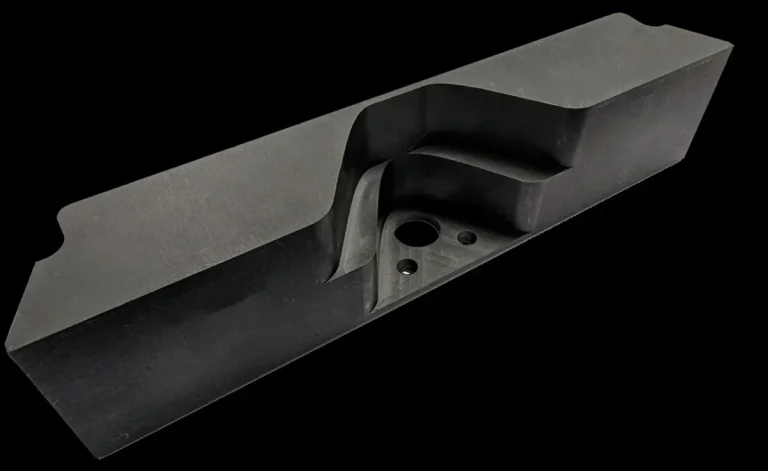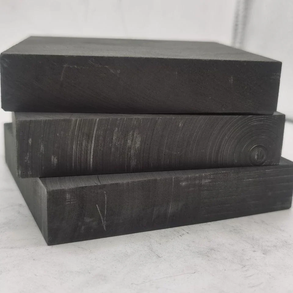
A graphite block datasheet can show two values for what appears to be the same property: one measured with the grain and another across it, or one parallel to a forming direction and another perpendicular. If the buyer treats those values as interchangeable, the problem does not stay on the datasheet. It can reach the machining drawing, the way a blank is cut from the block, and the orientation of the finished part in service.
Anisotropy means the material does not necessarily respond identically in every direction. In manufactured graphite, the extent and pattern depend on raw materials, forming route, heat treatment, and the internal texture created during production. The earlier molded, extruded, and isostatic graphite block guide explains how forming routes change the material. This article starts one step later: once directional data exists, how should a buyer or engineer use it?
For isostatic graphite, YB/T 4379-2014 remains a current Chinese industry product reference. Direction-specific test methods can also exist for individual properties; for example, YB/T 6046-2022 specifies a method for linear thermal-expansion coefficient of isostatic graphite. The existence of a property method does not mean every graphite grade has the same directional behavior. Direction must stay attached to the reported data.
Where Anisotropy Comes from in Formed Graphite
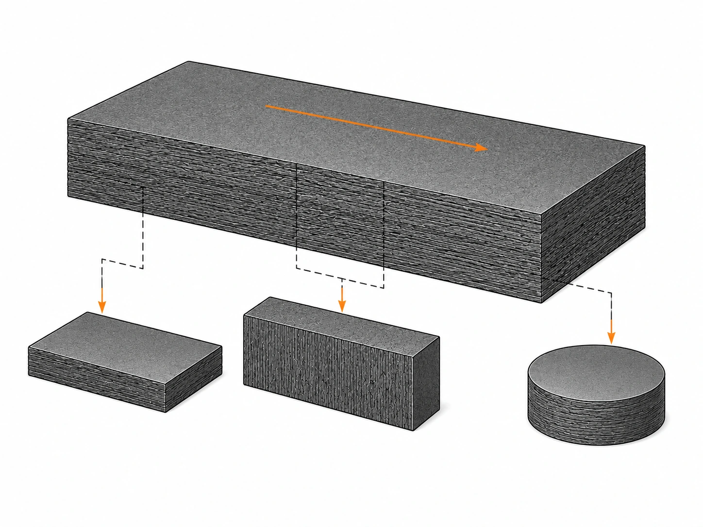
Anisotropy in formed graphite originates from the material texture created as coke particles, binder, pores, and later graphitized structure develop under a particular forming route. The important purchasing point is not to memorize a universal anisotropy ratio; it is to know whether the grade and block have a defined material direction.
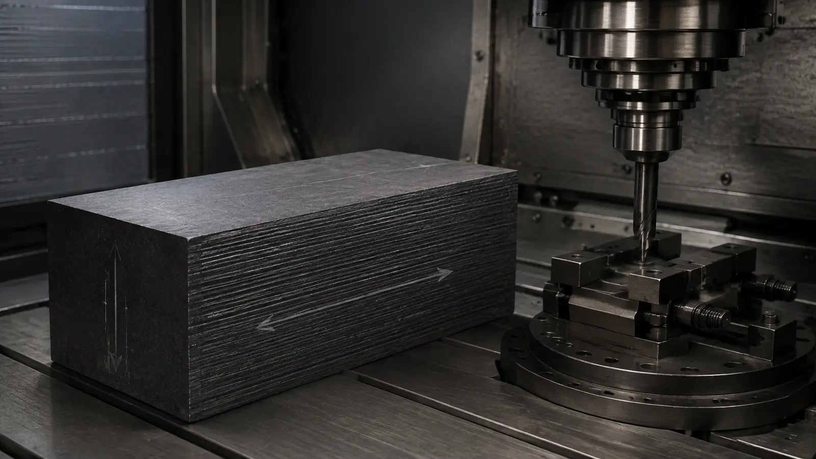
Extrusion applies material flow through a die, so particle and pore structure can develop a preferred direction along the extrusion axis. Uniaxial molding applies pressure mainly along one axis and can create another directional texture. Isostatic pressing applies pressure more uniformly around the compact and is often selected when lower directional variation is desired, but “isostatic” should not be translated into “perfectly isotropic.” Actual property data still governs the part.
Raw filler particle shape contributes as well. Graphitic particles are not ideal spheres, and elongated or plate-like constituents can orient during forming. Binder distribution, impregnation, repeated baking, and graphitization further influence the final microstructure. This is why two grades with similar density can still have different directional property relationships.
Section size matters because a large block is not a mathematical point. Processing gradients, sampling location, and test-piece orientation can affect reported values. When a datasheet shows one property number without direction, the buyer should not assume it represents every orientation. Ask how the specimen was taken and whether the value is typical, minimum, or another statistical statement.
The drawing implication appears early. If the finished component has one mechanically or thermally critical axis, that axis should be compared with the material direction before the blank is cut. Once machining removes the original block markings, recovering orientation from the finished black surface may be difficult.
Read Directional Property Data Correctly
Directional property values are comparable only when the direction labels refer to the same material axis and the test methods, units, specimen conditions, and data type are equivalent. “Parallel” on one datasheet may not mean the same physical direction as “with grain” on another unless the supplier defines it.
Start with vocabulary. Common descriptions include with grain, against or across grain, parallel to extrusion, perpendicular to extrusion, parallel to pressing direction, and perpendicular to pressing direction. Some suppliers use X/Y/Z directions on block drawings. The RFQ should ask for a diagram or explicit definition when the label is not self-explanatory.
Then check the property definition. Flexural strength, compressive strength, tensile strength, electrical resistivity, thermal conductivity, and thermal expansion are different measurements. A direction associated with one test cannot be copied automatically to another. The specimen orientation may refer to the long axis of the test piece, the heat-flow direction, electrical-current direction, or another measurement geometry.
Units and data status matter too. A typical value and a guaranteed minimum serve different purposes. A single supplier’s internal average cannot be compared directly with a customer acceptance limit unless the methods and statistical basis match. If two suppliers list “strength” but one means flexural strength and the other means compressive strength, the numbers do not belong in the same comparison column.
The graphite block datasheet guide provides a broader method for separating comparable from non-comparable supplier data. For anisotropy, add one rule: every directional property should carry an axis definition all the way into the comparison table.
| Datasheet field | Directional question | Risk if ignored |
|---|---|---|
| Forming route | Extruded, molded, isostatic, or another route? | Buyer assumes the same texture for unlike materials. |
| Direction label | Parallel/perpendicular to what? | Two opposite axes are compared as equivalent. |
| Test property | What physical quantity and specimen geometry? | Direction from one test is copied to another. |
| Data type | Typical, average, minimum, range, or guaranteed? | Qualification uses a marketing average as a release limit. |
| Sampling location | Where in the block was the test piece taken? | Local data is generalized to the entire stock size. |
Different properties can show different degrees and even different practical consequences of directional variation. A buyer should not create one universal “anisotropy factor” and apply it to strength, heat flow, electrical behavior, and dimensional change.
Mechanical properties depend on how pores, filler particles, binder-derived carbon, and microcracks interact with the applied stress. A direction that produces a higher flexural value in one grade does not automatically predict the same percentage difference in compression or tension. Use property-specific data.
Thermal behavior has another interpretation. Heat flow through the part follows the direction in which thermal conductivity is measured. A furnace fixture, heat sink, or heated mold can therefore be sensitive to how the material axis is placed relative to the intended heat path. If thermal expansion matters to fit or clearance, the coefficient should also be evaluated in the relevant direction and temperature range using a suitable method.
Electrical resistivity depends on current direction through the material. An electrode or electrically heated component can behave differently if the current path changes relative to the block texture. Again, this does not justify a generic claim that one direction is always “better.” The useful direction depends on the component’s function and the property being optimized.
Multi-property parts create trade-offs. The orientation that favors one mechanical property may not be the only design concern if heat flow, dimensional stability, erosion, or machining geometry pulls the decision another way. The engineering drawing should therefore identify which function is critical enough to control orientation rather than simply copying the supplier’s strongest directional value.
Translate Material Direction into Part Orientation
Material direction becomes useful only when it is translated into a defined orientation for the finished component. The chain is block axis → blank orientation → machining datum → finished-part functional axis.
Start with the original block. The supplier or stock controller should mark the forming direction or agreed axes on the block where directional control is required. The marking needs to survive sawing into smaller blanks; otherwise the first cut destroys the reference.
Next define the blank. A work traveler can record which block face corresponds to the part drawing datum. For a cylindrical part, the engineering team may care whether the cylinder axis is parallel or perpendicular to a material direction. For a rectangular plate, heat-flow or load direction may be tied to one long edge. The exact choice is application-specific.
Machining drawings should avoid ambiguous notes such as “machine with grain.” A clearer instruction identifies the graphite material axis and the part feature it must align with. If orientation is not functionally required, do not add the note simply because the datasheet contains directional data; unnecessary orientation controls can reduce nesting flexibility and increase material cost.
Orientation can affect yield. A large block may allow several parts to be nested efficiently only if they rotate relative to one another. If every part must use the same material axis, the cutting plan can consume more stock. That cost should be justified by service evidence rather than an untested assumption that aligned orientation is always safer.
For repeat orders, preserve the orientation requirement in the revision-controlled drawing or RFQ rather than an email comment. A supplier change, different stock size, or new machining subcontractor can otherwise remove the control without anyone realizing it.
Separate Machining Convenience from Service Performance
The easiest orientation to machine is not necessarily the orientation the component needs in service, and the orientation that maximizes one datasheet property may not create the lowest total manufacturing risk. Machining and service decisions should be evaluated separately before they are reconciled.
Sawing and machining can reveal edge behavior, dusting, chipping, or tool-load differences that depend on material texture and grade. If one orientation gives cleaner edges on a fragile feature, that is useful process evidence. But it should not automatically override a thermal or mechanical orientation requirement established for service.
Fixture design may also favor one blank orientation. A machinist may want the longest dimension to follow the original block length to reduce setups or material loss. Engineering may want a different axis aligned with heat flow. The drawing and manufacturing plan should make that conflict visible early, before a finished part is produced from an incorrectly oriented blank.
Prototype qualification can answer the trade-off. Machine otherwise comparable parts from different orientations when the application risk justifies it, then inspect machining quality and test the functional result under controlled conditions. This is stronger evidence than extending a general statement about grain direction into a specific component without a trial.
When no directional effect is meaningful for the finished use, allow the supplier or machine shop to optimize nesting. Orientation control is a cost-bearing requirement. It should be treated like a tight tolerance: applied where it protects function, omitted where it adds no verified value.
Supplier-to-supplier terminology is another source of error. One datasheet may use “parallel to grain,” another “parallel to extrusion,” and a third may show only a block sketch with arrows. Do not normalize those labels in a purchasing spreadsheet until the physical axes are confirmed. If the supplier cannot explain the direction basis, mark the values as non-equivalent rather than forcing them into a comparison.
Legacy parts need particular care because an old drawing may contain no orientation note even though the original supplier consistently cut the part one way. A replacement source can produce a dimensionally correct component from a different block orientation and unintentionally change directional properties. When reproducing a successful legacy part, review old inspection records, retained samples, stock-cutting notes, and failure history before deciding that orientation was irrelevant merely because it was not written on the drawing.
The same logic applies to repair and refurbishment. If a graphite component is machined smaller, re-faced, or duplicated from a worn original, the machine shop should not infer material direction from the visible wear pattern alone. Use the source record or a controlled engineering decision. Otherwise the repaired geometry may be correct while the replacement blank carries an unverified orientation.
For high-value parts, a simple orientation traveler can prevent this loss of information. The traveler can show the original block axes, saw-cut sequence, blank ID, drawing datum, and final part ID. Each operation signs off that the orientation marks were transferred before the next cut removed them. This is a low-complexity control compared with investigating an unexplained service difference after machining is complete.
Put Orientation Requirements on Drawings and RFQs
An orientation-controlled graphite part needs an RFQ and drawing that define material grade, forming route, block direction, part direction, test-data direction, and traceability. If one link is missing, the requirement can be lost between material purchase and machining.
Use this communication checklist:
- Material identity: grade and forming route, not only “graphite block.”
- Supplier axis definition: diagram or wording that defines pressing/extrusion/material directions.
- Required property data: property name, units, method, and direction.
- Part functional axis: drawing datum, heat-flow axis, load axis, current path, or other controlled feature.
- Blank marking: how orientation is preserved through sawing and machining.
- Inspection record: how the finished part is shown to follow the required orientation.
- Change control: notice if forming route, stock source, or orientation practice changes.
If the buyer is comparing isostatic grades, YB/T 4379-2014 provides a current Chinese product-standard context, but the RFQ must still state the directional data actually required for the project. YB/T 6046-2022 can provide a method reference when linear thermal expansion of isostatic graphite is part of the data package. Do not turn either standard into a universal orientation rule for every graphite component.
Finally, keep the material direction on the manufacturing record. A finished graphite part can look symmetrical even when the source block was not. If a later failure investigation cannot reconstruct orientation, the team loses one of the variables needed to compare failed and successful parts.
The practical rule is simple: directional data belongs to a direction. Preserve that definition from datasheet to block, from block to blank, and from blank to finished part. Only then can anisotropy become a controlled design variable instead of a confusing pair of numbers on a supplier PDF.
Orientation evidence should also be separated from dimensional inspection. A coordinate-measuring report can prove that the finished part meets size and position tolerances, but it does not prove how the blank was oriented in the parent block. If orientation is a requirement, the manufacturing record needs its own traceability field. That distinction prevents a complete dimensional report from being mistaken for complete material-orientation evidence.
When a part is not orientation-controlled, say so internally. An explicit “orientation not specified” engineering decision is preferable to leaving the issue ambiguous, because future sourcing teams can see that the omission was intentional rather than accidental, and can revisit it when the service condition or design changes later.