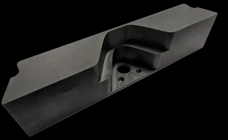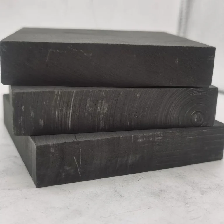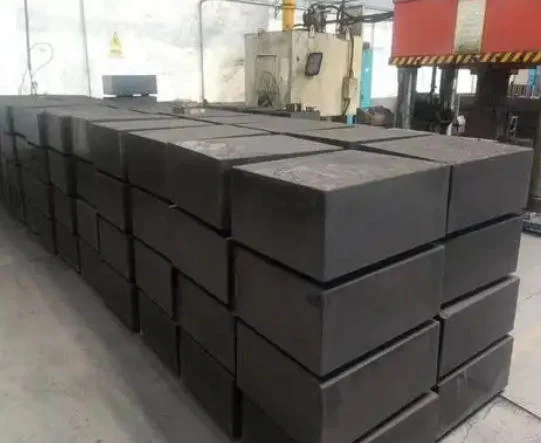
Graphite block is not one uniform product. The forming route changes pore structure, grain direction, available section size, mechanical strength, electrical resistivity and machining behaviour. A drawing can therefore be dimensionally correct and still be assigned to the wrong block family.
QDZRT Graphite supplies graphite block as a direct-use industrial material and as stock for custom graphite machined parts. The published core range remains 99%+ carbon and about 1.70–1.90 g/cm³ bulk density, with the final value tied to the selected grade. Furnace systems, EDM electrodes, molds, metallurgy and semiconductor-related components do not draw the same benefit from the same manufacturing route.
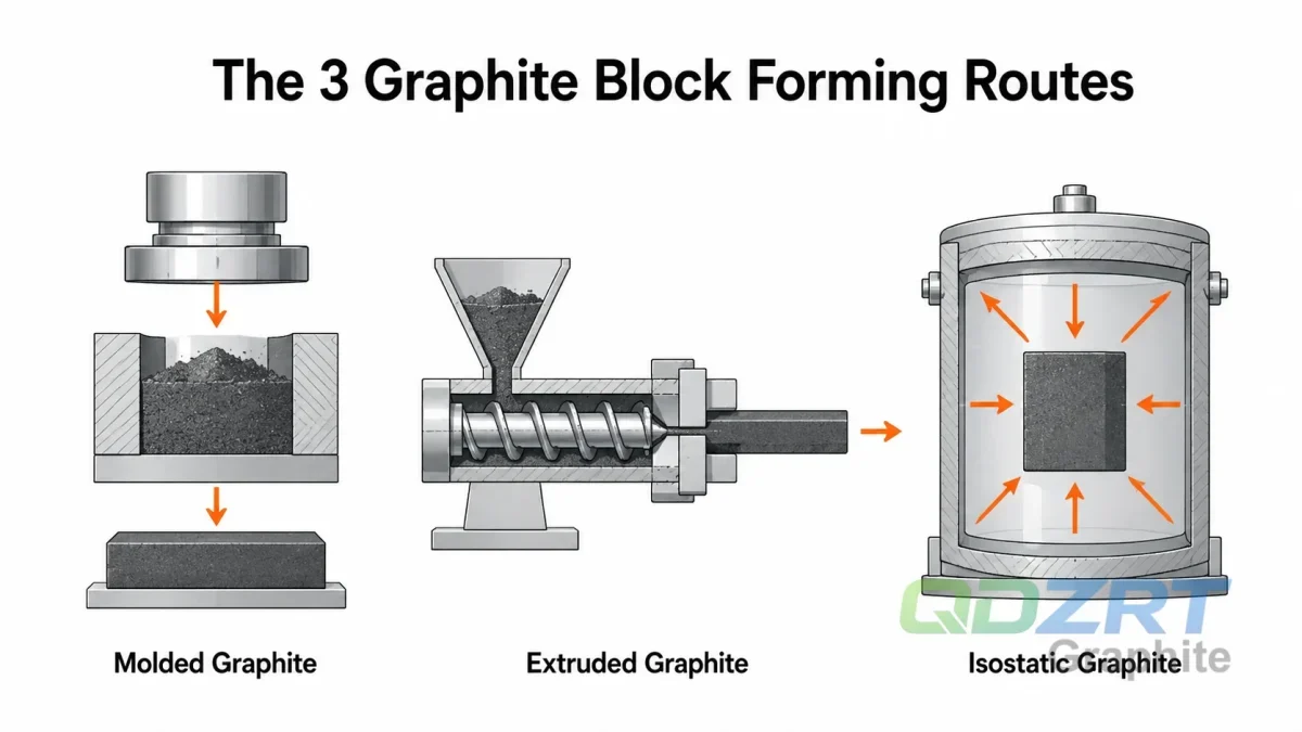
Three Ways to Make a Graphite Block
Industrial graphite starts with carbonaceous filler and binder. Mixing, forming, baking and graphitisation create the solid body; impregnation, rebaking or purification may follow. The forming step is the first major split. Uniaxial molding presses material in one principal direction. Extrusion pushes the mix continuously through a die. Isostatic pressing applies pressure through a fluid medium around the compact.
Those three routes leave different internal signatures. Pressed layers can produce measurable with-grain and against-grain behaviour. Extruded material develops a strong longitudinal direction and supports long sections. Isostatic pressure produces a more uniform, fine-grained body that is preferred when a part contains features in several orientations.
Forming is not the final operation. A green compact is baked so the binder carbonises, and the porous baked body is then graphitised at a much higher temperature. Impregnation and rebaking may repeat one or more times to close part of the open pore network. Purification can lower ash after graphitisation. Two blocks made by the same forming route can therefore carry different density, strength and purity because their filler recipe and post-forming treatment are different. The forming route narrows the material family, while the selected grade and post-forming treatment determine the final property limits.
The following ranges are illustrative industry examples for preliminary material comparison. They are not universal grade limits or our product guarantees. Actual values must be confirmed against the selected grade specification, test direction and batch documentation.
| Forming route | Bulk-density range | Grain range | Flexural-strength range | Compressive-strength range | Typical orientation note | Example stock section |
|---|---|---|---|---|---|---|
| Molded | 1.70–1.85 g/cm³ | 20–100 µm | 20–45 MPa | 45–90 MPa | Press axis identified | 300 × 300 × 100 mm |
| Extruded | 1.60–1.80 g/cm³ | 100–800 µm | 10–30 MPa | 30–65 MPa | Extrusion axis identified | Ø100 × 1000 mm |
| Isostatic | 1.75–1.90 g/cm³ | 5–30 µm | 35–70 MPa | 70–140 MPa | Near-isotropic | 200 × 200 × 200 mm |
Published product information from us covers grades with about 1.70–1.90 g/cm³ bulk density and sections from approximately 50 to 800 mm, subject to grade, forming route, geometry and stock availability.
The OSTI graphite behaviour model provides public technical context on nuclear-graphite density, microstructure and mechanical behaviour, but it does not define commercial stock dimensions or every value in this comparison. The approved purchase specification, controlled drawing and confirmed grade requirements remain the governing documents. The batch certificate provides evidence that the supplied material complies with those requirements.
Molded Graphite
Molded graphite is compacted in a closed die. Pressure acts mainly along the press axis, so filler particles and pores do not distribute identically in every direction. The process supports plates, blocks and medium-size billets with useful density and strength. It also accommodates finer material than many large extrusions. The pressing direction remains relevant from block selection through cutting and machining.
A molded block fits furnace fixtures, molds, crucible-related parts and machined components when the design can respect the material direction. It is also a practical stock option when an isostatic grade would add cost without improving the required function. The thermal management and high-temperature processing page shows the wider family of heat-oriented uses.
Direction must remain visible from block selection through machining. A plate cut across the pressing axis may show different flexural strength, thermal expansion or electrical resistance from one cut parallel to it. The effect varies by grade; it cannot be corrected by simply adding 2 mm of machining allowance.
Molded graphite also responds to impregnation. A first bake leaves open porosity because binder releases volatiles. Pitch or resin impregnation followed by rebaking can raise density and strength. The purchase description must distinguish a base grade from an impregnated grade because both may share similar outside dimensions while behaving differently in service.
Large molded pieces need attention at the centre. Pressing pressure does not always transmit through a thick compact as evenly as it does through a thin plate. Density readings taken only from an outer coupon can miss a central variation. For a large furnace component, the material agreement can state the sampling position and the direction of each mechanical test. For a simple support pad with generous section thickness, such detail may add no value. The inspection level has to follow the consequence of failure.
Extruded Graphite
Extrusion is the route for long, continuous sections. The mixed material passes through a die, producing rods, rectangular bars and large billets. Its principal production advantage is the ability to make long sections, while particle alignment follows the extrusion direction and makes longitudinal and transverse properties visibly different.
The route is efficient for electrodes, furnace rails, support pieces and long structural sections. Coarser grain can reduce the cost of large stock, yet it also limits the edge quality of tiny slots or thin ribs. A 0.8 mm wall cut in a 500 µm-grain body has little microstructural margin. A 5–20 µm fine isostatic grade gives a different machining result.
Extruded stock appears frequently in EDM and metallurgical supply chains, but not every extruded grade is an electrode grade. Electrical resistivity, ash, apparent density and grain size still require values. The EDM tooling application page and the article on choosing graphite block for EDM electrodes explain why material structure and electrode geometry must be considered together.
Long stock creates its own dimensional question. A 2000 mm bar can carry bow or twist that is invisible in a 100 mm sample. The quotation needs the as-supplied straightness basis, finished length and whether machining will reference the extrusion axis. Cutting several short electrodes from one long bar can be economical; machining a wide, flat plate across that bar can create avoidable waste.
Cross-section matters too. A round extruded rod, a square bar and a rectangular billet do not place material at the same distance from the die wall. Skin condition may differ from the core, and the first machining pass removes that surface layer. When the finished part uses almost the full as-extruded dimension, the stock tolerance and surface allowance need to be stated before the bar is ordered. A drawing that consumes 99% of the nominal section leaves no room for bow, die variation or saw damage.
Isostatic Graphite
Isostatic graphite is pressed with fluid pressure acting around the compact. Fine particles and uniform compaction create a relatively isotropic structure. That combination supports close-tolerance machining, small holes, thin walls and components whose load or heat path changes direction through the part.
Density is only one part of the advantage. A 1.82 g/cm³ isostatic body with 10 µm grain can produce cleaner edges than a 1.82 g/cm³ coarse body. Fine pores also affect impregnation, leakage and surface finish. For semiconductor-related hardware, purity and trace elements can become more important than the headline carbon percentage. For EDM, grain size and resistivity connect directly to wear and achievable surface condition.
Our team discusses these issues in graphite machined parts for semiconductor equipment and in the precision graphite machining guide. The more complex the geometry, the more important it is to confirm grain size, density and orientation before the blank is cut.
Fine-grain isostatic stock costs more per kilogram and is not available in every block size. A project can therefore fail at the stock stage even when the material properties look ideal. The finished envelope, required test direction and available billet size need to be checked together.
Purity also changes how the blank is handled after machining. A standard industrial part may be cleaned to remove loose graphite dust and packed in a sealed bag. A high-purity component can require dedicated cleaning materials, restricted contact surfaces and analytical confirmation of selected elements. Those controls cannot be inferred from the word “isostatic.” They must appear on the drawing, order or agreed specification.
How Grain Direction Affects Machining
Graphite is machinable but brittle. Its pores and grains guide crack initiation, and the forming route decides how uniform those features are. Toolpath direction, clamping surface and the location of thin sections can therefore expose anisotropy that a material data sheet averages away.
A long extruded electrode cut parallel to the axis may machine consistently along its length. The same grade cut into a broad transverse plate may show different expansion or strength. Molded stock has a pressing axis that must be related to the drawing. Isostatic stock reduces, but does not eliminate, local variation.
The cutting sequence changes the stress state. Removing a large proportion of a blank from one side before the opposite face is released can expose internal variation as bow. Symmetrical roughing leaves material on both sides, gives the part time to stabilise and reserves a final finishing pass. That approach is especially useful for plates, rings and frames with unequal wall sections. It does not make graphite elastic; it limits how much imbalance is introduced during machining.
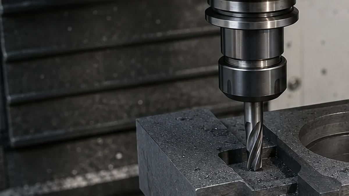
A tight dimensional tolerance cannot compensate for an unsuitable grade, grain structure or orientation. The following allowances are preliminary quoting examples rather than fixed machining rules. Final blank size depends on the selected grade, as-supplied tolerance, surface condition, bow or twist, workholding method, cutting sequence, feature location and inspection requirements.
| Machining feature | Example finished size | Initial allowance | Grain-size consideration | Orientation note |
|---|---|---|---|---|
| Flat plate | 300 × 200 × 20 mm | 3–6 mm | 20–100 µm may be usable; verify tolerance and surface requirements | Mark press or extrusion axis |
| Thin wall | 1.0–2.0 mm wall | 2–4 mm on blank | Fine-grain grades may be considered; verify wall thickness and breakout risk | Avoid weak transverse edge |
| Small hole | Ø1.0–3.0 mm | 5–10 mm end allowance | Fine-grain grades may reduce breakout; verify hole size and method | Hole axis versus grain recorded |
| Deep pocket | 50–120 mm depth | 4–8 mm base allowance | Select according to corner radius and edge requirements | Stable support around opening |
| Long rod | Ø40 × 1200 mm | 3–5 mm diameter, 10–20 mm length | Coarser extruded grades may be usable for suitable geometry | Extrusion axis along length |
The final blank and machining allowance should be confirmed against the actual grade, stock condition, orientation, holding method and inspection plan before production begins.
Machining graphite can generate airborne dust. The NIOSH Pocket Guide entry for synthetic graphite provides occupational-exposure information and measurement-method references. Appropriate local extraction, housekeeping, work practices and personal protection should be selected through a workplace exposure assessment and the applicable occupational-health requirements.
Drawing review is covered in more detail in graphite-parts drawing review, tolerance confirmation before ordering and the article on thin walls and small holes.
Choosing a Block Size That Does Not Waste Material
The cheapest kilogram can produce the most expensive finished part when the stock size is poorly matched. Stock size is therefore a technical selection variable because it affects orientation, machining allowance, yield and final part performance.
Start with the finished bounding box, then add machining allowance, saw loss and a holding zone. A finished plate of 300 × 200 × 20 mm typically needs a blank near 310 × 210 × 28 mm; ordering a full 400 × 400 × 100 mm block would waste material without adding function. A hollow ring should be nested from stock that permits the centre to be reused when the material and traceability rules allow it.
Orientation can override simple nesting. Turning a drawing 90° may reduce waste but put a weak transverse direction across a loaded rib. The same conflict appears when a large isostatic billet is available only in one standard diameter. Stock utilisation decisions must prioritise the performance direction over the saw plan.
Quantity changes the calculation. One prototype can be cut from an oversized warehouse block because avoiding a new production batch saves time. A repeat order of 200 pieces justifies a dedicated nesting plan and possibly a stock size closer to the finished envelope. Yield must be calculated by usable finished pieces, not by comparing gross kilograms. Saw kerf, corner damage, test coupons and rejected surface zones all consume material before the first completed part is packed.
Our article on sourcing graphite block for OEM work covers RFQ detail, while common graphite block buying mistakes addresses grade and machining-scope mismatch.
What to Put on the Purchase Order
A purchase order needs enough information to identify the material independently of the product name. Record forming route, supplier grade, carbon or ash requirement, bulk density, maximum grain size, flexural or compressive strength when relevant, resistivity when relevant, purification state and impregnation state. Add the required stock dimensions with tolerance and state the forming direction on each block.
For machined supply, identify the controlled drawing revision in the inquiry and have the drawing ready for follow-up by email or another agreed secure channel. Identify datums, critical dimensions, surface condition, edge breaks, inspection method and quantity. State whether our team supplies a raw block, saw-cut blank or finished component. Packaging must protect corners and prevent graphite dust from contaminating adjacent cargo.
Inspection terms need units and sampling. “High density” is not an acceptance limit; “bulk density ≥1.80 g/cm³ by the agreed method” is. “Fine grain” is not a maximum grain size. A dimensional report should identify whether every part is measured or whether a lot sample is used. If chemical purity matters, list the elements or ash limit that can release the lot. A carbon percentage without a test method can describe several different calculations.
A workable order line could read: “Fine-grain isostatic graphite block, bulk density ≥1.80 g/cm³ by the agreed test method, nominal maximum grain size 20 µm according to the approved grade specification, fixed carbon ≥99.9% by the agreed analytical method, blank 320 × 220 × 35 mm, six pieces, all faces saw cut, batch material certificate.” That text does not replace the drawing; it makes the material identity testable.
Prepare the finished envelope, forming-route preference, property limits, application atmosphere and drawing revision for review. Start the inquiry through the contact page; after we reply, send the controlled drawing or CAD file by email or another agreed secure channel. Our team can then compare available stock with the required direction and quote either a block, a machined blank or a completed part.