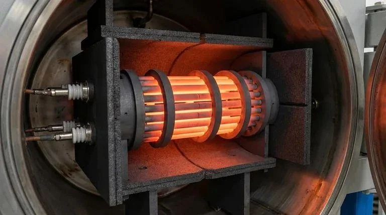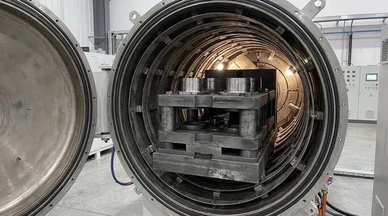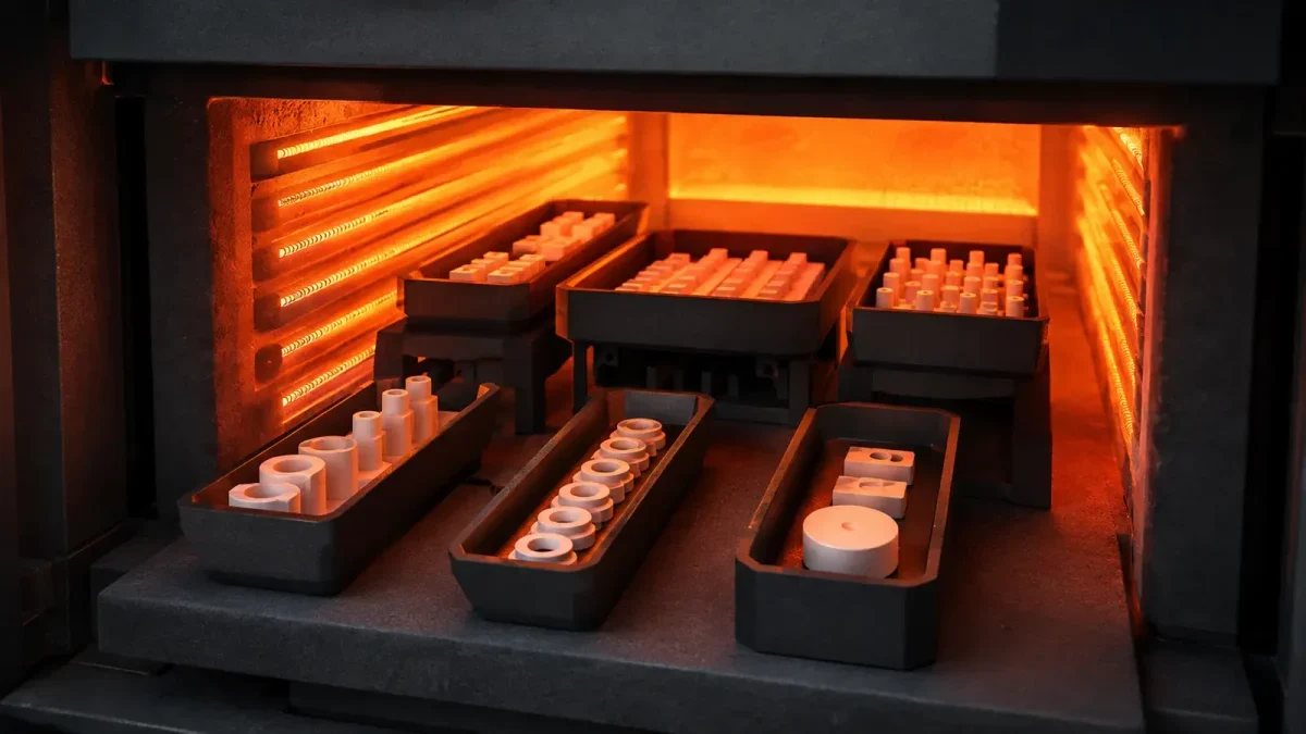
A graphite boat or tray is easy to underestimate because its geometry often looks simple. In a furnace, however, it is a structural component exposed to payload weight, support reactions, temperature gradients, repeated heating and cooling, handling, and sometimes strict contamination requirements. A tray that survives the peak temperature can still warp, crack at a support transition, chip during unloading, or become unsuitable because its surface condition changes.
The design question is not simply whether graphite can withstand the peak temperature, but whether this tray can carry this payload through the actual thermal cycle without losing functional geometry.
Define Payload, Support Points, Temperature, and Atmosphere
Begin with the actual furnace arrangement. Record the payload mass and distribution, the number and location of support points, the orientation of the tray, the heating and cooling sequence, and the atmosphere during every stage in which the graphite remains hot.
Payload distribution matters because total mass does not describe bending. A concentrated load near the center of a long span creates a different structural problem from the same mass distributed across the full floor. Stacked workpieces can also shift the center of load or create local contacts that were absent in the original design.
Support conditions deserve the same attention. A tray supported continuously along two rails behaves differently from one resting on isolated pads. Furnace furniture can move, wear, accumulate deposits, or be installed with imperfect level. The graphite design should therefore identify where support is intended and where unintended contact must be avoided.
Temperature must be described as a cycle. Heating rate, soak, cooling sequence, loading condition, and temperature uniformity can influence dimensional stability. The maximum furnace setpoint alone cannot describe thermal gradients across a large tray.
Atmosphere is an independent requirement. Vacuum, inert gas, reducing conditions, and periods of air exposure should be stated explicitly. Graphite oxidation risk cannot be judged from a generic temperature statement without knowing oxygen exposure and process timing.
The first design input should capture payload, footprint, support layout, thermal cycle, atmosphere, loading/unloading method, reuse expectation, and critical interfaces.
Choose Grade by Strength, Purity, and Thermal Requirements
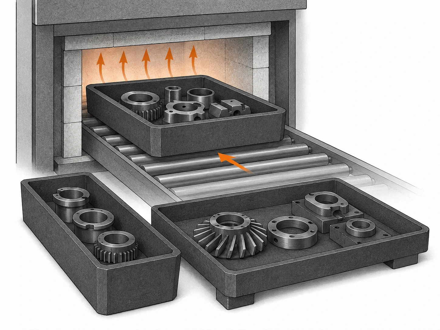
Material selection starts with the load path and process requirement, then uses the datasheet to compare candidate grades. Density, grain structure, mechanical properties, thermal behavior, purity, blank size, and consistency between production lots may all matter.
For a structural tray, strength data are only useful when the geometry and support arrangement are known. Thin floors, long unsupported spans, narrow ribs, lifting holes, and abrupt section changes can control the design even when the bulk material has suitable nominal properties.
Purity becomes important when the furnace process or workpiece has a contamination budget. The requirement should come from the process owner. A supplier should not assume that a generic “high-purity graphite” label satisfies a semiconductor, metallurgical, ceramic, or laboratory process without knowing which elements or contamination mechanisms are critical.
Thermal properties should likewise be connected to geometry. Heat transfer through the tray can influence how quickly different areas of the load respond, but furnace heaters, insulation, radiation view factors, contact surfaces, and payload arrangement are also part of the thermal system. Selecting a grade by thermal conductivity alone does not guarantee uniform workpiece temperature.
For repeat supply, keep the approved material identity with the drawing; do not substitute another grade solely because its density looks similar.
Wall, Rib, and Support Geometry: Follow the Load Path
A good tray makes the load path understandable. The floor carries the payload into ribs, walls, rails, feet, or other support features, and those features transfer the load to the furnace structure. Geometry that interrupts that path can create local stress concentrations.
Ribs are not automatically beneficial. They can increase section stiffness, but their location, thickness, transition radius, machining direction, and connection to the floor all matter. A rib that ends abruptly in a highly loaded region may introduce a new stress concentration. Deep pockets machined between ribs can also leave thin residual sections that are vulnerable during handling.
Wall thickness should be treated functionally. Increasing every wall adds material, machining time, thermal mass, and weight. Making every wall thin reduces those costs but can increase damage risk. Choose wall and rib geometry by balancing span, payload, handling, machining access, thermal response, and the expected service history.
Openings require special review. Vent holes, slots, lifting features, alignment holes, and process-clearance windows interrupt the section. Their edges and spacing should be checked against the load path rather than added after the main tray has been designed.
Support surfaces should be clearly dimensioned and inspectable. If a tray is intended to sit on rails, the drawing should identify those rail-contact faces as functional surfaces. Flatness or relative height requirements should be applied where they control stable support, not indiscriminately to every external face.
Warpage and Dimensional Stability During Thermal Cycling
Warpage is a system outcome, not simply a material defect. Geometry, support, temperature gradients, payload, machining history, and repeated cycling can all contribute to dimensional change.
The first defense is symmetry where the process allows it. Strongly asymmetric pockets, ribs, or wall sections can produce uneven thermal response. When asymmetry is required by the workpiece, designers should identify which dimensions are critical after heating and which are only important for room-temperature assembly.
Support repeatability is equally important. If a tray is placed differently from cycle to cycle, measured dimensional changes may partly reflect changing support conditions. Defined locating and support features make inspection data more meaningful.
Large trays should also be inspected using a consistent datum strategy. Measuring an unsupported graphite tray on one surface and then measuring it on a different fixture can create apparent variation unrelated to permanent deformation. The inspection method should therefore specify how the part is supported during measurement.
During process development, dimensional records can be taken at selected cycle intervals. Early cycling data should show which features move first in the actual furnace process and which dimensions deserve routine monitoring. Once the pattern is understood, the inspection plan can focus on the dimensions that affect loading, workpiece position, furnace clearance, or product quality.
Loading, Unloading, and Handling Damage
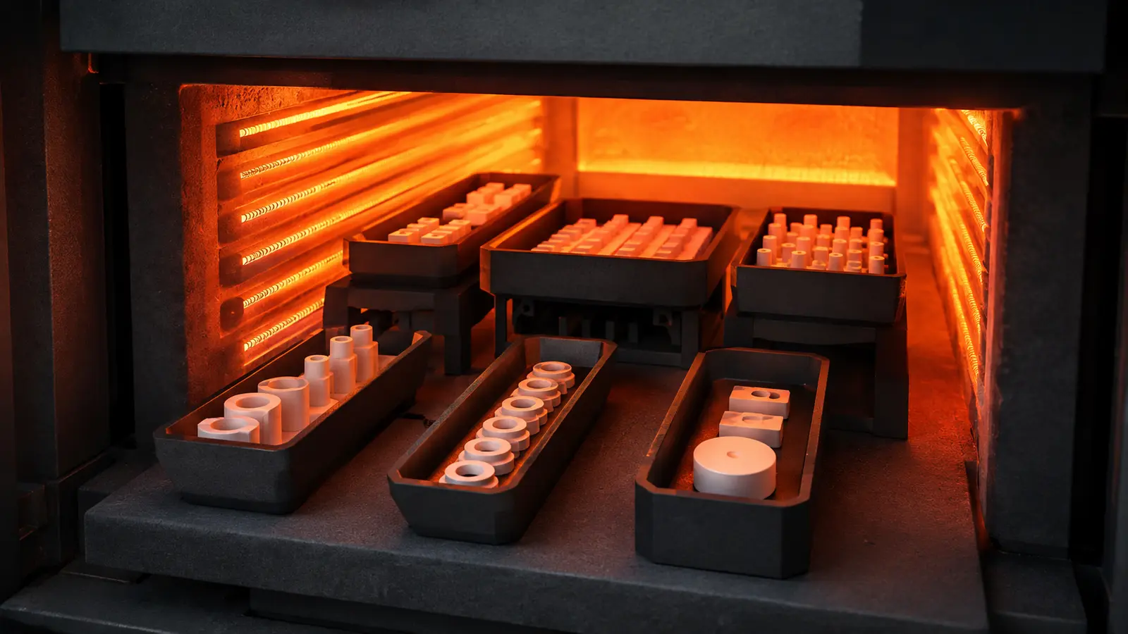
Many furnace trays fail outside the furnace. Graphite components can experience impact, edge loading, leverage, or accidental point contact while operators load workpieces, remove product, clean deposits, or move the tray between storage and the furnace.
The design review should therefore include human and mechanical handling. Ask how the tray is lifted, where hands or tools contact it, whether a robot or fork enters beneath it, and whether operators ever use a corner or opening as a lifting point.
If dedicated lifting features are required, they should be designed as part of the load path rather than improvised after machining. Their edges, local section thickness, and relationship to the payload need review.
Workpiece loading can also damage the tray. Heavy parts placed rather than lowered, hard ceramic components dragged across a contact face, or fixtures inserted with poor alignment can create chips and scratches that accumulate over time. Loading instructions can therefore be part of the controlled process for expensive reusable furnace furniture.
Storage is another overlooked stage. Trays should be supported so that long spans are not left under unintended bending load. Contact with hard metal edges, mixed stacking, and contamination from dirty shelving may also undermine a carefully controlled furnace process.
Inspection, Repair, and Replacement Criteria
Inspection should distinguish cosmetic change from functional damage. A surface discoloration or minor mark on a noncritical face may have little effect, while a small crack at a support transition or a chipped locating feature can change how the tray carries load.
Create an inspection map tied to the drawing. Typical zones include support faces, high-load ribs, corners, lifting features, workpiece locating surfaces, thin sections, holes, and areas known to accumulate process residue.
Dimensional inspection should focus on features that affect function: overall support geometry, critical flatness relationships, locating dimensions, furnace clearance, and workpiece position. Measuring every dimension after every cycle can consume time without improving process control.
Repair options are process-specific. Removing deposits, lightly dressing a noncritical surface, or replacing a separate insert may be acceptable in one application and prohibited in another. Any repair that changes a qualified contact surface, critical dimension, contamination state, or load-bearing section should be reviewed before the tray returns to service.
Replacement criteria should be documented before obvious failure. Examples of evidence to monitor include crack initiation, repeated chipping, dimensional drift, loss of stable support, surface deterioration at critical contacts, oxidation damage, or inability to clean the tray to the required condition. The acceptable limit for each item belongs to the qualified process rather than a generic graphite rule.
Create a Drawing Package for Repeat Supply
A repeatable furnace tray requires more than a 3D shape. The drawing package should capture the material, critical geometry, datum system, surface requirements, inspection points, and revision history that made the qualified part work.
At minimum, identify the approved graphite grade or controlled material requirements, overall dimensions, critical wall and rib sections, support faces, workpiece locating features, tolerances, required surface conditions, and any cleaning or packaging restrictions.
Matched sets should be identified if interchangeability is not guaranteed. If multiple trays stack together or share locating hardware, the drawing should state whether each item must be independently interchangeable or supplied as a controlled set.
Revision control is especially important after furnace trials. Small geometry changes made during development—an added relief, changed rib, larger corner radius, revised support height, or modified loading feature—should be transferred into the production drawing rather than left as shop-floor knowledge.
QDZRT Graphite can machine custom graphite boats, trays, and furnace components from customer drawings. For a meaningful DFM review, the drawing should be accompanied by the furnace and load information that explains why the geometry exists.
Design Input Checklist
Before releasing a graphite boat or tray for quotation, confirm the following:
- payload mass, footprint, and distribution are defined;
- intended support points and contact faces are identified;
- furnace atmosphere and air-exposure stages are known;
- thermal cycle is described beyond the peak temperature;
- critical workpiece locating features are marked;
- wall, rib, opening, and lifting geometry has been reviewed against the load path;
- contamination or purity requirements come from the process owner;
- measurement support and datum strategy are defined;
- handling and storage methods are considered;
- inspection and retirement criteria exist for reusable trays;
- material identity and drawing revision are controlled for repeat orders.
Design Review: What Changes When the Tray Gets Larger
Scaling a graphite tray is not a simple proportional exercise. When span increases, the relationship between payload, support spacing, floor thickness, ribs, and handling changes. A geometry that is robust at one size can become sensitive to bending or warpage when its unsupported distance grows. The larger tray may also experience a stronger temperature gradient from center to edge because the furnace and load no longer heat it uniformly.
When tray size changes, recalculate the support layout, unsupported spans, handling method, and load position instead of scaling only the outer dimensions. Confirm that the furnace rails or pads still contact the intended faces and that the workpiece load remains inside the supported region. Review lifting and unloading as well: a tray that could be handled safely by two operators at a smaller size may require dedicated lifting features or equipment after scaling.
If rail spacing, loading pattern, or stack height changes, recheck the tray even when its drawing has not changed. Those furnace conditions are part of the load system.
Packaging and Incoming Verification for Large Furnace Furniture
Large graphite trays can be damaged before they ever reach the furnace. Packaging should support the component at stable locations and prevent part-to-part contact, edge impact, and leverage across long unsupported spans. The packaging design should also preserve any cleanliness requirement established after machining.
At incoming inspection, verify drawing revision, material identity where required, obvious transport damage, critical support faces, and the dimensions that control fit in the furnace. A full dimensional report may not be required for every repeat order, but the acceptance plan should identify which features are essential for interchangeability.
First-Article Evidence for a New Tray Design
A first article is not proven by room-temperature dimensions alone. Record the material, tray revision, support condition, payload arrangement, and critical dimensions, then check the same functional features after the initial furnace trials.
After the first furnace trials, recheck support faces, locating geometry, clearances, and sections exposed to bending or repeated handling. Fixed-view photographs can supplement the measurements when chipping, oxidation, or contact marks matter.
If the first article requires a geometry correction, update the controlled drawing before ordering the next batch. A shop-floor instruction such as “leave this rib thicker” or “relieve this corner” should not remain tribal knowledge. The revision should identify what changed and why, so replacement trays are not manufactured to an earlier geometry that already failed qualification.
For repeat orders, reduce incoming inspection to the material, drawing revision, critical support/locating features, and transport condition shown to matter during first-article qualification.
Record the Loaded Configuration
Photograph or sketch the actual payload arrangement with the tray revision. Workpiece count, spacing, stacking, and support pads can change bending and thermal response even when the graphite drawing is unchanged.
If the selected graphite grade carries directional property data, preserve the material axis from blank to finished tray; the graphite block anisotropy guide explains how to keep that orientation traceable without imposing it where the tray design does not need it.
References and Sources
- ASTM C651-20 — Flexural Strength of Manufactured Carbon and Graphite Articles Using Four-Point Loading at Room Temperature. A material-characterization reference for flexural strength, not a furnace-tray design allowable.
- ASTM D02.F0 — Manufactured Carbon and Graphite Products standards catalogue. Provides the current family of graphite material test methods for density, strength, ash, moisture, and related controls.