A graphite susceptor can couple energy from an induction field and transfer heat to a workpiece, but coupling alone does not define a successful design. The real objective is a controlled workpiece temperature field, which depends on the induction system, graphite properties, susceptor geometry, workpiece position, insulation, atmosphere, and measurement method.
For that reason, a susceptor should not be specified by a generic graphite grade and one target temperature. The validated geometry is part of the process recipe.
How the Susceptor Couples to the Induction Field
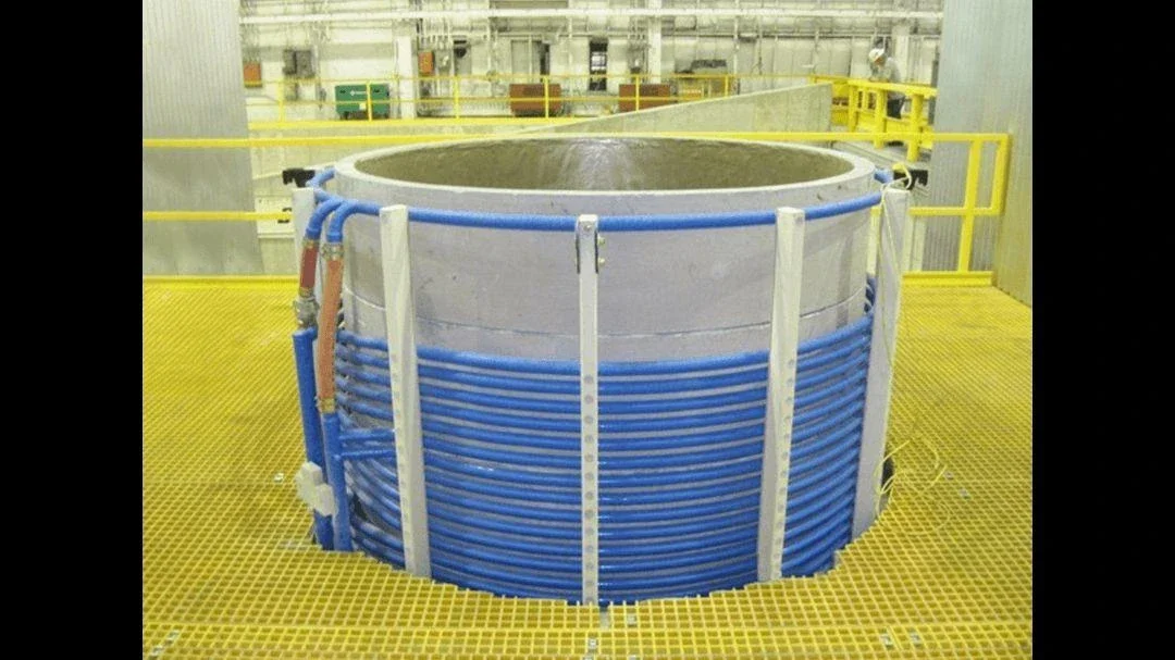
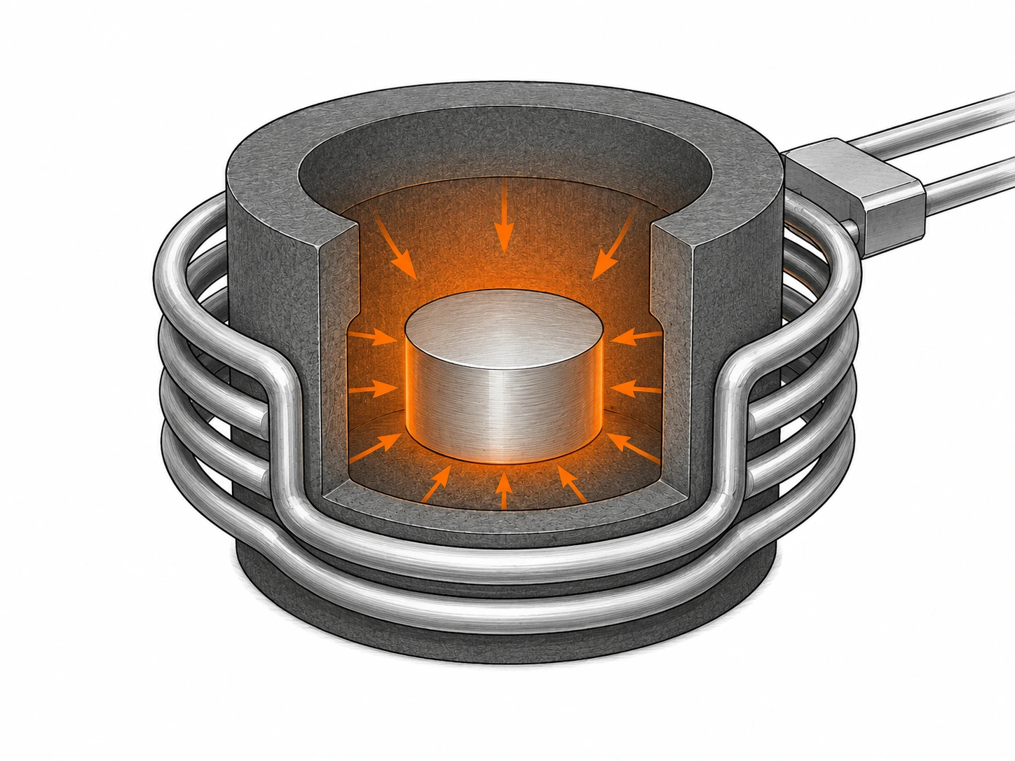
Induction heating creates an alternating electromagnetic field. Conductive material placed in that field can develop induced currents and heat through electrical losses. In a graphite susceptor, the field distribution and current paths depend on coil arrangement, frequency, material electrical properties, geometry, and the surrounding load.
This means that two susceptors made from the same graphite can heat differently if their wall thickness, diameter, length, slots, openings, or position relative to the coil changes. The workpiece itself can also influence the system.
A quotation drawing should therefore preserve the dimensions that were validated in the induction setup. Treating the susceptor as a simple container and changing its section to save material can change heating behavior even if the new part still fits mechanically.
Electrical Resistivity and Material Consistency
Electrical resistivity matters to induction response, but it has to be evaluated with geometry, frequency, coil arrangement, and the rest of the thermal system. Graphite grades also differ in structure, density, mechanical properties, thermal behavior, purity, available blank size, and property consistency.
If a process has already been qualified with a particular grade, replacement supply should control material identity or use an approved equivalency process. A substitute with similar density but materially different electrical behavior may change the thermal response.
Property direction should be considered where the graphite manufacturing route produces anisotropy. Supplier data should be interpreted according to the reported orientation and test method rather than copied into a model without context.
For new development, the material specification should identify which properties are process-critical and which are simply descriptive. This keeps the procurement specification connected to measurable process performance.
Geometry and Wall Thickness Shape the Heating Pattern
Geometry determines where induced current can flow and how heat moves through the susceptor. Wall thickness, corners, end features, openings, shoulders, and transitions can all influence local heating and thermal gradients.
Increasing wall thickness changes the current path, thermal mass, conduction distance, and warm-up response; it does not guarantee a more uniform temperature field. A thinner wall reduces thermal mass but may increase fragility or create a different electromagnetic and thermal response.
Abrupt geometry changes deserve special attention because they can coincide with both electromagnetic and thermal nonuniformity. The design team should identify hot or cold regions through measurement or validated simulation rather than assume that visual symmetry guarantees thermal symmetry.
Machining tolerances also matter selectively. Dimensions that control coil spacing, workpiece clearance, or critical wall section may need tighter control than external features with little effect on heating. The drawing should make that distinction.
Workpiece Position and Thermal Uniformity
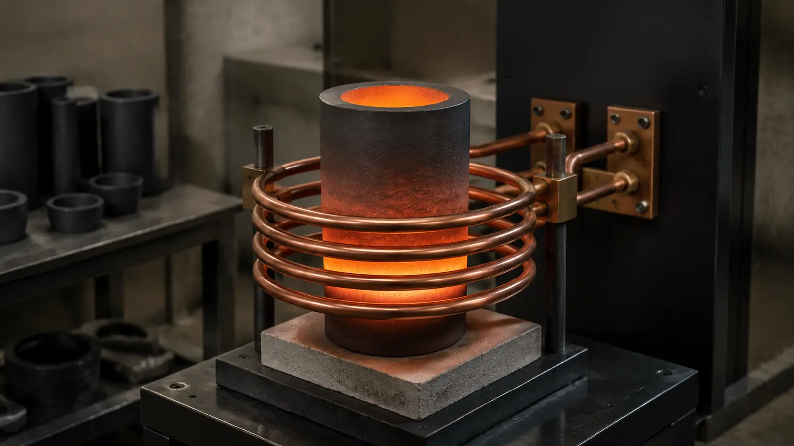
The susceptor is only one component of the thermal system. Workpiece location inside or around it can change radiative view, conductive contact, gas flow, and the distance from locally hotter graphite regions.
Repeatable workpiece positioning is essential. A change in height or offset can shift the temperature field even when the susceptor itself is unchanged.
Fixtures, spacers, lids, insulation, and shields should be included in the validation configuration. A temperature map developed without the production loading hardware may not represent the final process.
When multiple workpieces are processed together, loading density and spacing should also be controlled. Adding more parts can change thermal mass and radiative exchange. Production qualification should define the load configuration rather than validate an empty susceptor and assume identical behavior at full load.
Temperature Measurement and Validation
Thermal uniformity must be measured. The appropriate method depends on temperature range, atmosphere, optical access, workpiece, and equipment. Thermocouples, optical pyrometry, calibrated process sensors, or other validated methods may be used, but each has limitations.
Measurement location is as important as the instrument. A single reading near the susceptor wall does not prove that the workpiece center, top, bottom, and critical interfaces share the same temperature history.
During development, define measurement points before the trial. Record the coil setup, power program, susceptor revision, material grade, workpiece load, insulation configuration, atmosphere, and sensor locations. Without that configuration record, a successful temperature profile can be difficult to reproduce.
Set allowable temperature variation from the workpiece process requirement and validate it at the locations that control product quality.
Hot Spots, Oxidation, and Common Failure Clues
Visible local changes can provide diagnostic information. Uneven surface appearance, localized oxidation, cracking, deformation of thin features, or repeated damage at the same location can indicate a thermal, electromagnetic, mechanical, or atmosphere-related problem.
A hot spot should not automatically be blamed on “bad graphite.” Check coil position, electrical settings, geometry revision, workpiece loading, insulation, contact conditions, atmosphere, and measurement system before changing material.
Oxidation requires particular care. Induction applications can bring graphite to high temperature rapidly, but the oxidation risk depends on oxygen availability and exposure time. Vacuum or inert operation does not eliminate risk during loading, venting, leakage, or cooling in air.
Cracks can also originate from handling or geometric stress concentration rather than heating alone. Failure analysis should therefore preserve the damaged part and compare the crack location with drawings, support conditions, and thermal records.
Convert the Validated Geometry into a Repeatable Drawing
Once a susceptor performs correctly, freeze the information that made it work. The production drawing should identify graphite grade, critical wall sections, coil-related dimensions, workpiece locating features, datums, tolerances, surface requirements, and revision history.
Do not rely on a sample part as the only master. Samples wear and can be measured differently. A controlled drawing and process record make replacement supply more reliable.
If geometry is changed to improve machinability or reduce cost, treat the change as a process change where it can affect heating. Revalidate the temperature field rather than assuming dimensional interchangeability equals thermal interchangeability.
Susceptor Validation Record
A useful validation record includes:
- susceptor drawing and revision;
- graphite grade and material lot where required;
- induction equipment and coil configuration;
- relevant operating program;
- workpiece material, quantity, and position;
- insulation and shielding arrangement;
- furnace or chamber atmosphere;
- temperature measurement method and sensor locations;
- observed hot/cold regions;
- dimensional inspection before and after trials where relevant;
- approved geometry and any rejected revisions.
Inputs for a Susceptor DFM Review
Send the 2D drawing or 3D model, approved graphite grade if known, induction-system constraints relevant to geometry, workpiece arrangement, atmosphere, critical dimensions, quantity, and inspection requirements.
QDZRT Graphite can review the graphite component for blank selection, machining feasibility, thin features, inspection access, and repeat production. Electromagnetic settings and process-temperature acceptance remain part of the customer’s qualified induction-heating system.
Development Trials: Change One Variable at a Time
Susceptor development can become confusing when material grade, wall thickness, coil position, insulation, and workpiece loading are changed in the same trial. If the temperature field improves or worsens, the team may not know which change caused it. A controlled development sequence reduces that ambiguity.
Start with a baseline configuration and record it completely. Then change one dominant variable, such as wall section or workpiece position, while keeping the remaining setup as constant as practical. Measure the same temperature locations and record the same cycle data. This does not eliminate all interaction between variables, but it creates more useful evidence than a series of undocumented trial-and-error changes.
When a geometry revision is successful, assign a new drawing revision and link the trial data to that revision. Do not rely on a handwritten note such as “use the thicker one” because replacement manufacturing months later needs an exact definition.
Thermal Uniformity Is a Workpiece Requirement
The susceptor itself does not need to have a visually uniform color or identical surface temperature everywhere unless that condition supports the workpiece requirement. The real acceptance criterion belongs to the product being heated. Some processes care about a narrow temperature distribution across a component, while others care about a heating rate, a minimum temperature at one location, or a controlled thermal gradient.
That distinction affects sensor placement. Measuring only the hottest visible graphite region can exaggerate apparent process temperature, while measuring one convenient external surface can miss a cold region inside the workpiece. Validation points should be chosen from the process risk rather than from instrument convenience.
If optical measurement is used, emissivity assumptions, line of sight, window condition, and whether the instrument is viewing graphite or the workpiece should be documented. If contact sensors are used during development, their attachment can itself alter local heat transfer. The measurement system therefore belongs in the validation record.
Material Substitution and Repeat Supply
When a qualified susceptor needs replacement, a supplier may have access to several graphite grades that appear similar by density or strength. Substitution should not be based on one headline property. Electrical resistivity, anisotropy, thermal response, grain structure, purity, and dimensional capability can all influence the validated system.
For repeat supply, keep the approved grade on the controlled drawing. If an alternative is necessary, compare the relevant electrical, thermal, structural, and dimensional properties, then revalidate heating in the actual induction system. A part can be dimensionally interchangeable without being thermally equivalent.
Lot-to-lot consistency also matters when a production process is sensitive. The acceptance plan can identify which material certificate fields are needed and whether incoming resistance or dimensional checks are used before installation. The scope should be proportional to process risk rather than copied from a generic high-purity specification.
Failure Analysis Before Redesign
When a susceptor cracks, oxidizes locally, or produces a new hot spot, preserve the failed component long enough to investigate it. Record the crack location, wall section, workpiece position, coil position, insulation state, atmosphere events, and any recent changes to the power program. Compare the failure with previous components.
A crack beside a machined opening may suggest a geometry or handling issue. Localized surface loss near a hot region may point toward oxidation or a changed atmosphere sequence. A temperature imbalance after replacing a susceptor can suggest a material, dimensional, or installation difference.
Changing the graphite grade without this evidence can hide the true cause. The better sequence is observe, map the damage to the drawing and process, identify the likely mechanism, then decide whether material, geometry, coil setup, insulation, or operating procedure should change.
Inspection of the Finished Susceptor
Inspection should focus on dimensions that can alter electrical coupling, workpiece position, thermal mass, or mechanical fit. Critical wall sections, diameters, slots, openings, locating features, and interfaces with insulation or supports deserve more attention than nonfunctional exterior faces.
A susceptor should also be checked for shipping damage before installation. Chipped edges or cracks near thin current-carrying sections can become failure origins during heating. If the part is supplied as a repeat replacement, compare the critical dimensions and material identity with the approved revision rather than relying only on visual similarity.
For high-purity processes, final cleaning and packaging should be specified separately from dimensional inspection. A part can be geometrically correct yet unsuitable if it has been contaminated after machining.
Cost Reduction Without Losing the Validated Thermal Design
Once a susceptor is qualified, cost-reduction proposals should distinguish electrical/thermal geometry from noncritical manufacturing details. Removing material from a current-carrying wall, changing a slot, altering the workpiece position, or substituting graphite can affect heating and should be treated as a process change.
Lower-risk changes may include nonfunctional external reliefs, packaging improvements, or simplified inspection on noncritical dimensions. Document the change, but reserve thermal revalidation for revisions that can affect the current path, wall section, coil spacing, workpiece position, or thermal mass.
The objective is not to freeze every manufacturing detail forever. It is to protect the small set of dimensions and material characteristics that actually control the induction-heating result.
Spare Susceptors and Revision Control
If a process depends on a qualified susceptor, spare parts should be ordered before the existing component fails. The spare should carry the same controlled drawing revision and approved material identity. When it arrives, inspect critical dimensions and store it in a way that prevents impact, oxidation exposure, or contamination before installation. A spare that has been modified informally or mixed with an earlier revision should not enter the validated process without review.
Freeze Coil-to-Susceptor Position as a Controlled Interface
A validated susceptor drawing is incomplete if production can reposition the part relative to the induction coil. Record the locating features, axial position, radial clearance, and assembly references that reproduce the qualified electromagnetic geometry. A replacement part that is dimensionally correct but installed at a different position can produce a different heating field.
When coil maintenance changes the surrounding hardware, treat the positional relationship as part of revalidation. This separates a susceptor-material problem from a changed induction geometry before the graphite grade is blamed.
Separate Heating Uniformity from Mechanical Fit
Two susceptors can fit the same chamber and still produce different temperature fields. Treat mechanical interchangeability and thermal equivalence as separate acceptance questions.
Keep a Thermal Map with the Susceptor Revision
When a susceptor geometry passes validation, store the temperature-map result with that exact drawing revision and loading arrangement. The map does not need to become a permanent production test for every part. Its purpose is to show which geometry was proven and to provide a baseline when a wall section, opening, coil position, insulation package, or workpiece location changes later.
Susceptor behavior can also be sensitive to the direction attached to resistivity and thermal data. Use the graphite block anisotropy guide when the blank has directional property reporting, and preserve the validated susceptor orientation in the production drawing.
References and Sources
ASTM C611-21— Electrical Resistivity of Manufactured Carbon and Graphite Articles at Room Temperature. Provides a room-temperature resistivity test reference; induction performance at operating temperature still requires process-specific validation.ASTM C651-20— Flexural Strength of Manufactured Carbon and Graphite Articles Using Four-Point Loading at Room Temperature. Useful for material characterization where structural features also matter.