When a conductive coating misses its electrical target, the graphite certificate is only one place to look. The same formulation can also pass an electrical check and still be commercially unusable because the coating settles, becomes too viscous, develops surface defects, loses adhesion, or varies from batch to batch. These outcomes point to a system problem in which graphite type, particle-size distribution, morphology, surface condition, chemistry, dispersion, binder, solvent or vehicle, solids level, film thickness, cure, and application method work together.
The useful selection process therefore starts from the failure or target observed in the finished coating. If resistance is too high, the next question is whether the graphite network failed to form, whether the graphite was poorly dispersed, whether the binder fraction or film thickness changed, or whether the selected powder simply does not create the required contact structure in that formulation. If the film is conductive but unstable, the buyer must identify whether settling, agglomeration, viscosity, coarse particles, chemistry, or process variation is responsible before tightening the raw-material specification.
China’s current graphite and particle-analysis standards provide a measurement framework without turning one powder into a universal conductive grade. GB/T 19077-2024 is the current national laser-diffraction reference, GB/T 3520-2024 covers graphite fineness testing, and GB/T 3521-2023 is the current national chemical-analysis reference for graphite. The formulation trial must still determine which measured properties actually control the coating result.
Start from the Coating Failure or Electrical Target
The electrical target and the coating failure mode determine which graphite variables should be investigated first. A raw-material comparison without a defined film target can generate a large amount of powder data while leaving the actual formulation problem unresolved.
Define the electrical result on the finished specimen, not only on the powder. The relevant result may be sheet resistance, volume resistivity, continuity between defined points, shielding-related performance, heating behavior, antistatic behavior, or another project-specific electrical measure. The test specimen, electrode arrangement, film thickness, cure state, conditioning, substrate, and measurement geometry should remain controlled during grade comparison because each can change the apparent result.
Then record the non-electrical failure modes. A conductive coating that cannot be applied consistently is not qualified merely because one laboratory coupon meets an electrical target. Watch for settling during storage, hard sediment, viscosity drift, poor wetting, agglomerates, screen or filter blockage, roughness, pinholes, weak adhesion, cracking, inconsistent film build, edge defects, and cure changes.
| Observed result | Graphite variable to investigate | Formulation/process variable to hold or verify |
|---|---|---|
| Electrical resistance too high | Graphite type, PSD, morphology, dispersion state, purity only where chemistry is relevant | Graphite loading, binder ratio, film thickness, cure, substrate, test geometry |
| Large electrical variation across the panel | Agglomeration, coarse tail, dispersion uniformity, lot consistency | Mixing sequence, application thickness, drying/cure uniformity |
| Viscosity rises or coating becomes difficult to apply | Fine fraction, surface condition, powder structure, moisture | Vehicle, solvent, solids content, dispersant, mixing energy and temperature |
| Settling or hard sediment | Particle distribution, density-related handling, agglomeration | Rheology package, storage time, shear history, vehicle |
| Surface defects or rough film | Coarse particles, agglomerates, morphology | Coating gap, filtration, substrate, film thickness |
This failure-first approach prevents premature conclusions. A lower D50 is not automatically the cure for high resistance. A higher fixed-carbon number is not automatically the cure for poor conductivity. Either change may help in a specific formula, but the trial must show the mechanism.
Choose Graphite Type by the Function It Must Perform
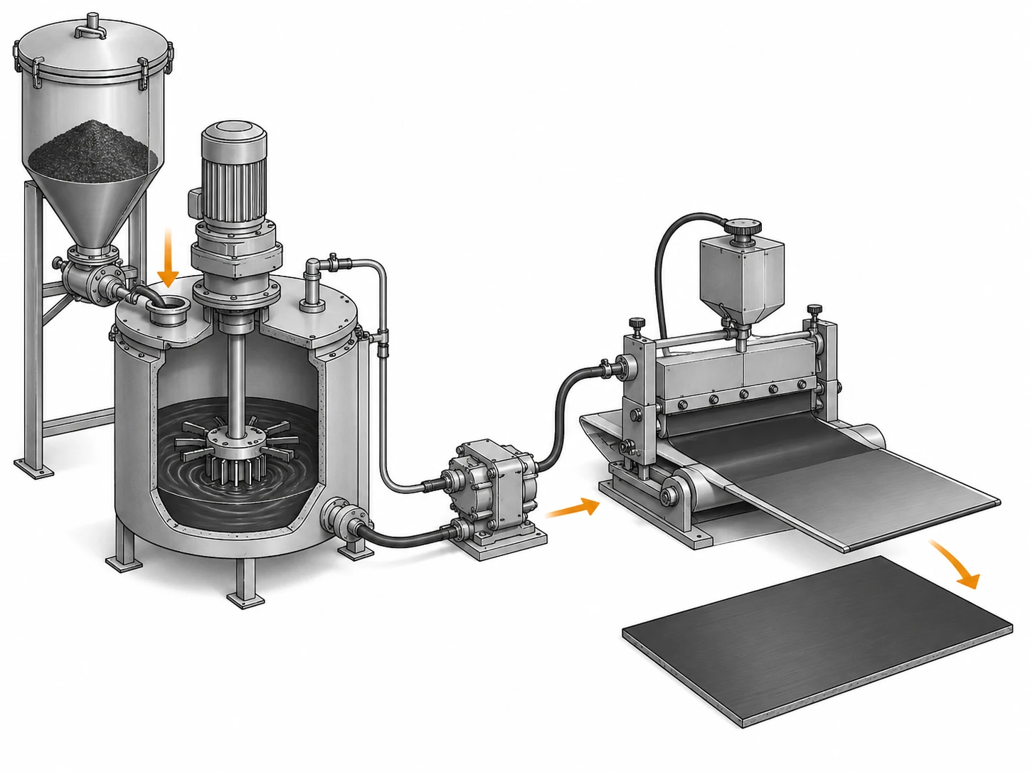
The graphite type should be selected by the contact structure and processing behavior the coating needs rather than by a general ranking of natural, synthetic, flake, or micronized graphite. Different powder routes can produce useful conductive coatings, but they do not necessarily build the same particle network in the same binder.
Platelet-like particles can create extended contact areas and directional structures in a film, while more granular or angular particles may pack and connect differently. Milling can reduce particle size but also change morphology. Synthetic processing can produce a wide range of particle shapes and structures. The words “natural” and “synthetic” therefore provide feedstock context, not a complete prediction of electrical behavior.
The natural versus synthetic graphite powder guide separates feedstock route from measurable properties such as PSD, morphology, chemistry, and bulk behavior. For a conductive coating, use that comparison only to choose candidate families. The final choice should come from the cured-film result and the process stability of the qualified formula.
A formulation may also use graphite with other conductive fillers. If so, do not attribute the final network entirely to the graphite. Carbon black, metal particles, fibers, nanotube-type additives, or other conductive phases can change the percolation path, viscosity, dispersion demand, and cost structure. Keep those ingredients fixed when comparing graphite grades unless the trial is intentionally testing a hybrid system.
Particle Size and Distribution vs Film Formation
Particle-size distribution affects how graphite is dispersed, packed, and exposed through the coating film, so it should be controlled against film formation rather than against one isolated size number. D50 describes the central population; the coarse tail and fine fraction often explain the defects that D50 misses.
A coarse tail can become visible in a thin film, interfere with a narrow coating gap, create local thickness variation, or remain as partially wetted agglomerates. Fines can increase total surface that the liquid phase must wet, influence viscosity, and alter the amount of binder effectively available around the particles. A broad distribution may improve packing in one system and destabilize rheology in another.
The dedicated micronized graphite PSD guide explains why D50, D90, tails, and measurement method should be read together. In a conductive coating, that information becomes useful only after it is connected to film thickness, roughness, dispersion, and electrical continuity.
Do not tighten PSD before checking whether the apparent size problem is actually an agglomeration problem. A powder can meet its incoming size distribution and still enter the coating as larger clusters if storage, wetting, dispersion sequence, or shear is inadequate. Conversely, an aggressive dispersion step can break weak agglomerates and change the effective particle population seen by the coating process.
When screening grades, record the incoming PSD and then inspect the wet and cured coating. The meaningful question is whether the qualified distribution remains reproducible enough to support the same application process. If a narrow upper-tail limit removes a repeatable surface defect, it belongs in the specification. If a small D50 change has no measurable effect, it may be better treated as a monitoring field.
Dispersion Quality Can Override a Good Powder Specification
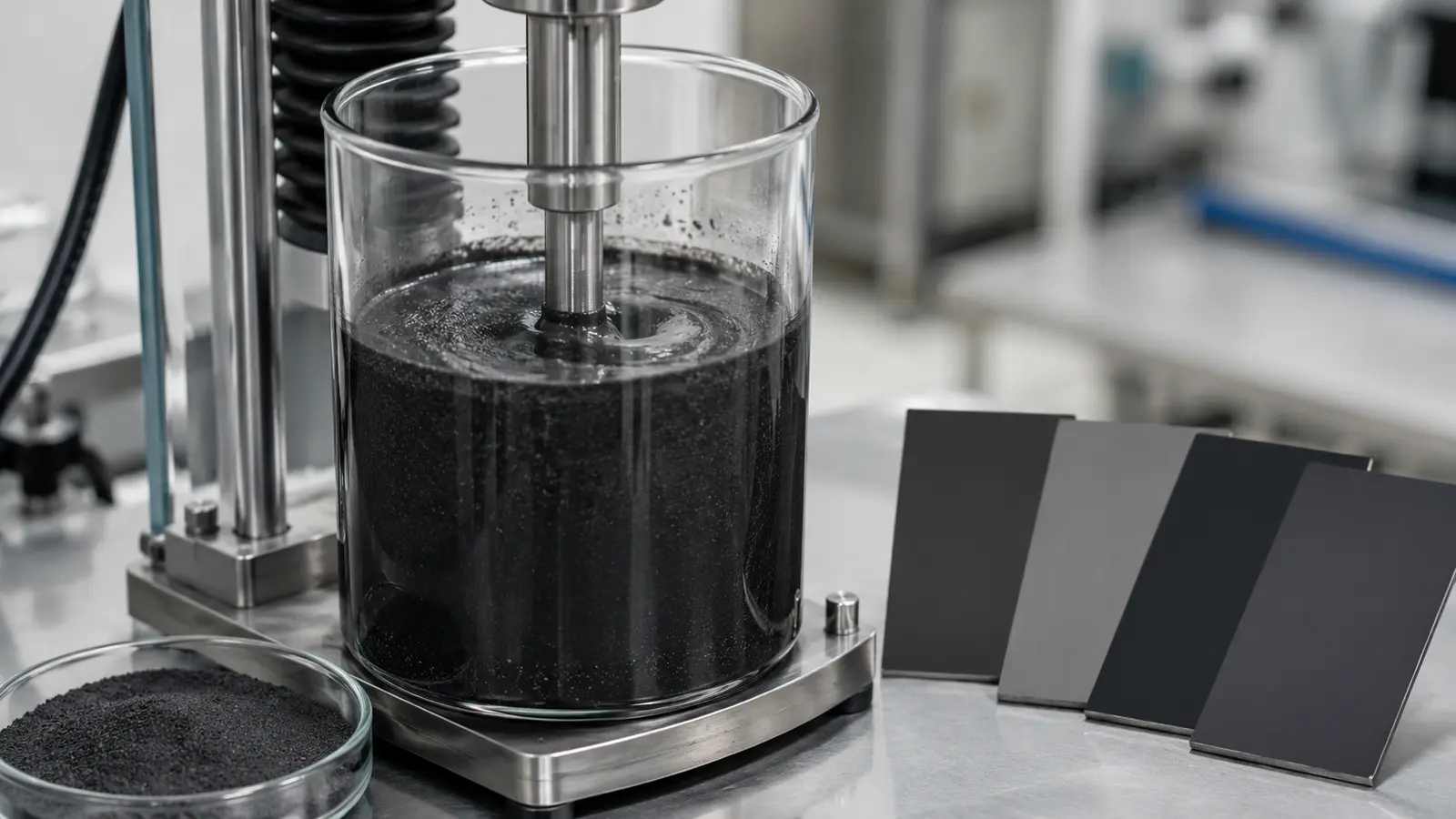
Dispersion quality can dominate the coating result even when the graphite powder itself meets every agreed incoming specification. The buyer therefore needs a dispersion procedure that is controlled tightly enough to separate powder differences from process differences.
Start with addition sequence. Adding dry graphite into a fully developed high-viscosity system can wet differently from introducing it into a lower-viscosity vehicle or pre-dispersion. The order in which binder, solvent, additives, dispersant, and graphite are combined can change agglomerate breakdown and the amount of air trapped in the mixture.
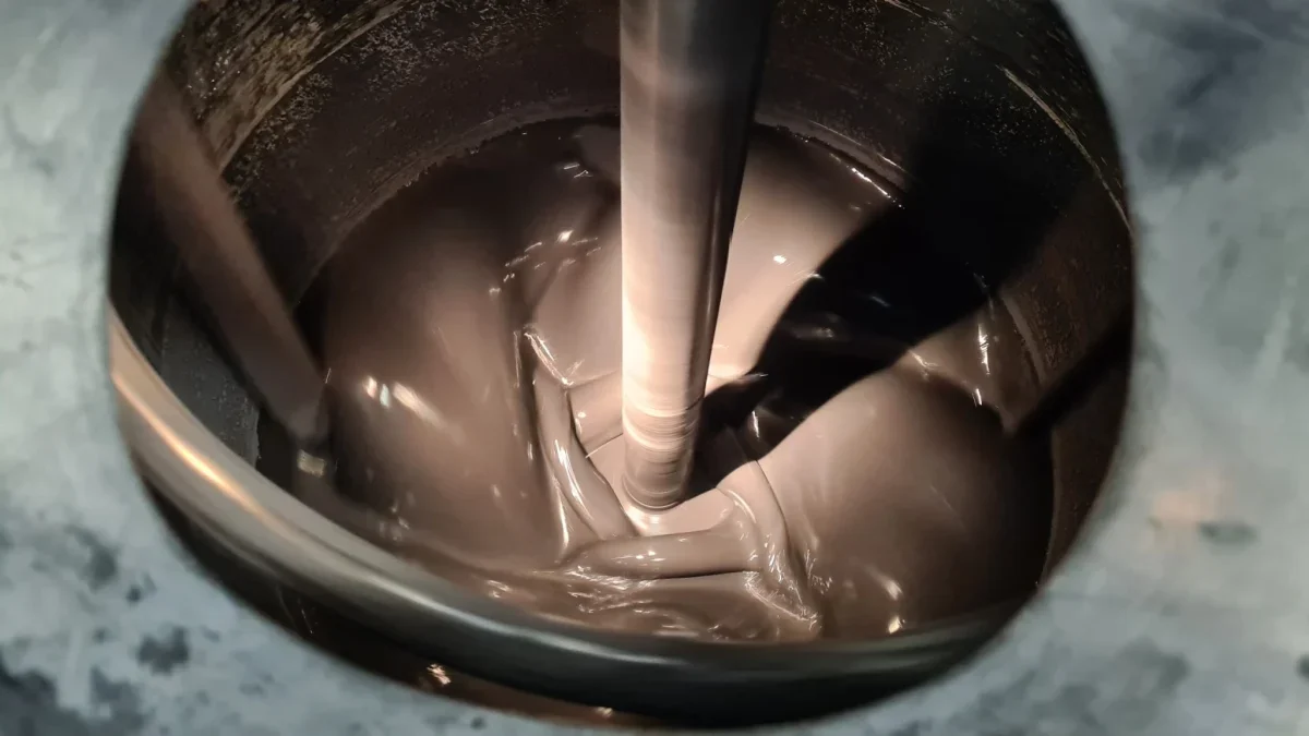
Mixing energy is another variable. Equipment type, rotor or blade geometry, batch size, vessel geometry, temperature, time, and shear history all influence the dispersion state. The objective is not to apply the maximum possible shear. Excessive processing can change temperature, solvent balance, particle shape, binder behavior, or equipment wear. The useful condition is the one that produces a stable coating and can be repeated at production scale.
Judge dispersion with more than visual appearance. A coating can look uniformly black while still contain electrically important agglomerates or local graphite-poor regions. Compare viscosity or rheology behavior, drawdown or coated-film appearance, thickness, electrical result at several positions, and storage stability. Where microscopy or another dispersion assessment is used, define the sample preparation so comparisons are meaningful.
A failed electrical result should therefore trigger two parallel checks: powder identity and dispersion execution. Retest with retained material using the qualified dispersion procedure before rejecting a lot solely on finished-film resistance. If the retained lot reproduces the failure while the control lot does not, the material difference becomes more credible.
Purity and Contaminants: Tie Limits to the Coating System
Purity and contaminant limits should be based on the coating chemistry, substrate, service environment, and customer requirements rather than the assumption that the highest available purity is always the best purchase choice.
Fixed carbon can be a useful screening field, but it does not identify which impurities are present. Ash can include several mineral components. Trace metals, sulfur, moisture, residual ions, or other chemistry fields may matter in a corrosion-sensitive system, an electronics-related coating, a chemically reactive binder, or a controlled contamination environment. In a less sensitive industrial coating, the same impurity may have no demonstrated effect at the levels encountered.
GB/T 3521-2023 provides a current national graphite chemical-analysis reference. The order should still state which results are contractual and why they matter. Do not convert a wide laboratory chemistry panel into a purchase specification without application evidence.
The high-purity graphite powder impurity guide treats this at the application level. For conductive coatings, the practical sequence is narrower: identify the failure mechanism, choose the chemistry fields capable of causing it, qualify a working range, and then control those fields on repeat lots.
Moisture deserves separate attention because it can affect powder handling, dispersion, and some binder systems even when it is not treated as an impurity in the same sense as ash or trace elements. If moisture matters, define sample conditioning and the test basis so the number can be reproduced.
Run a Controlled Formulation Trial and Freeze the Variables
A controlled formulation trial should change the graphite candidate while keeping the other variables fixed enough to show whether the powder caused the observed difference. Changing graphite type, graphite loading, dispersant, mixing time, and film thickness at the same time produces a result that cannot be traced back to one decision.
Use a baseline formulation with identified raw-material lots. Record graphite lot, addition level, addition sequence, mixing equipment, time, temperature, batch size, coating method, wet and dry film thickness where measured, substrate, cure or drying condition, conditioning, electrical test method, and the non-electrical acceptance checks.
| Trial stage | Keep fixed | Compare | Decision |
|---|---|---|---|
| Powder-family screen | Formula, graphite loading, dispersion procedure, coating and cure | Candidate graphite types | Which family can reach the required film function? |
| PSD confirmation | Graphite family and chemistry as close as practical | Qualified particle distributions | Which distribution controls surface and electrical consistency? |
| Dispersion confirmation | Powder lot | Controlled mixing sequence/energy within the process window | Is the issue raw material or dispersion execution? |
| Chemistry confirmation | Formula and PSD | Relevant purity/impurity levels | Does chemistry change compatibility or performance? |
| Repeat-lot confirmation | Approved formula and process | Additional lots of the selected grade | Is production performance repeatable? |
Include a control material in important trials. A retained qualified lot processed beside a new lot is one of the most useful ways to separate normal day-to-day formulation variation from a genuine powder shift.
Translate the Winning Trial into a Purchase Specification
The purchase specification should preserve the graphite characteristics and process controls that made the winning trial repeatable, without turning every laboratory observation into a contractual limit.
Separate four layers. The first is material identity: graphite family, approved grade or qualified sample reference, and lot traceability. The second is release data: PSD fields, fixed carbon or chemistry fields, moisture, and any other property proven necessary for acceptance. The third is supporting information: morphology, bulk behavior, or other monitoring data that help diagnose changes. The fourth is application confirmation: the formulation and finished-film test that proves the powder still performs the required function.
For PSD, specify the agreed method and the distribution features connected to actual film behavior. For chemistry, list only the fields linked to compatibility, contamination, or customer requirements. For packaging, consider moisture protection, segregation, and handling if those can change the powder state. For change control, identify supplier changes that require notification or requalification.
A practical RFQ for a new conductive-coating project should include the binder or vehicle family, substrate, graphite function, current grade if one exists, target or qualified particle-size information, known chemistry restrictions, graphite addition basis, dispersion equipment, film-build range, cure or drying route, electrical acceptance method, and the main process failure currently being solved. Those details let QDZRT Graphite discuss candidates against the application rather than answer with a generic “conductive graphite” label.
When a conductive coating fails, move backward in this order: confirm the electrical and film test, confirm film thickness and cure, confirm dispersion execution, compare the retained control lot, review PSD and agglomeration, then review the chemistry fields that have a plausible mechanism. That sequence turns a vague material complaint into a controlled purchasing decision.
Do not use the COA as a substitute for the formulation record. The COA describes the delivered powder under agreed test methods; the formulation record describes how that powder was converted into a working film. Keep both. If a future lot is inside every incoming limit but the coating drifts, the formulation record provides the reference needed to check mixing, film build, cure, substrate, and test execution before the raw material is blamed. If the process is stable but the lot trend shows a meaningful change in PSD, chemistry, or another monitored field, the same records support a focused supplier investigation.
For continuous production, retain a small sample from qualified lots when practical and define a simple escalation rule. A minor monitoring-field shift with no process effect may justify observation rather than rejection. A change that crosses a proven release limit or reproduces a coating failure should trigger containment and requalification. This approach keeps the specification tied to risk instead of turning normal analytical variation into unnecessary production stoppage.
For coatings that are stored before use, include an aging check in the qualification plan. Compare electrical result, viscosity or application behavior, visible settling, redispersion effort, and film condition at the time points that matter to the plant. A graphite that disperses well immediately after mixing can still create a production problem if the formulation settles hard, changes application behavior, or produces a different film after storage. Keep this test in the formulation qualification, not on the powder COA.
References and Sources
- National Standard Information Public Service Platform — GB/T 19077-2024, Particle size analysis—Laser diffraction methods. Current Chinese national laser-diffraction reference; implemented 1 May 2025.
- National Standard Information Public Service Platform — GB/T 3520-2024, Test method for fineness of graphite. Current Chinese national graphite-fineness test standard.
- National Standard Information Public Service Platform — GB/T 3521-2023, Methods for chemical analysis of graphite. Current Chinese national graphite chemical-analysis reference.