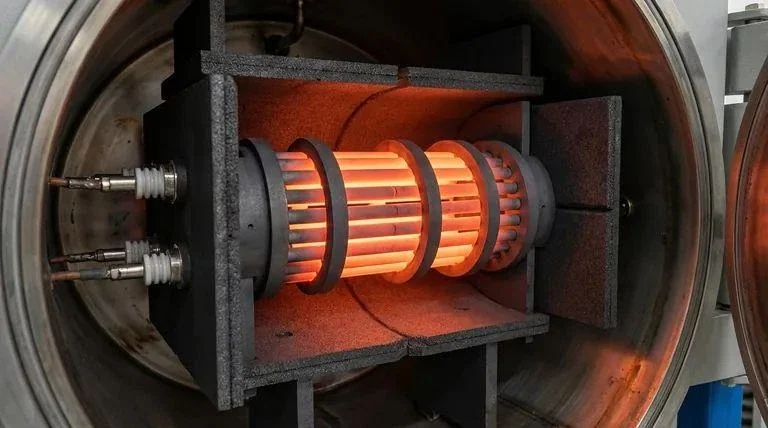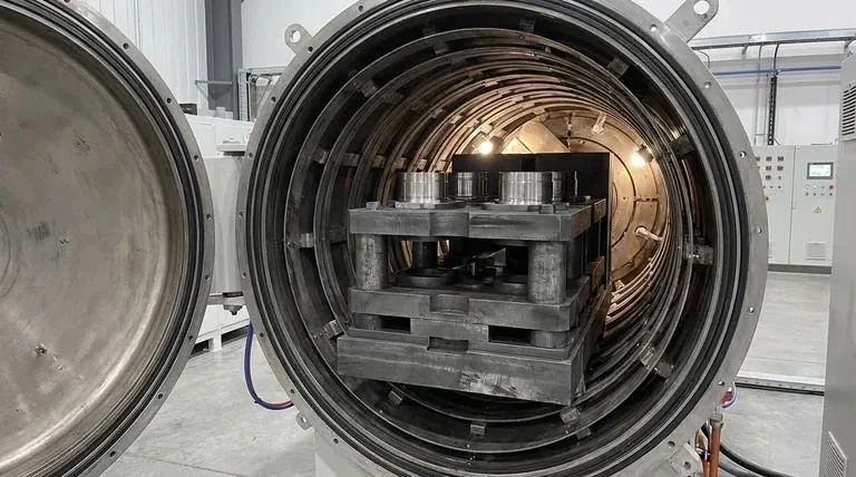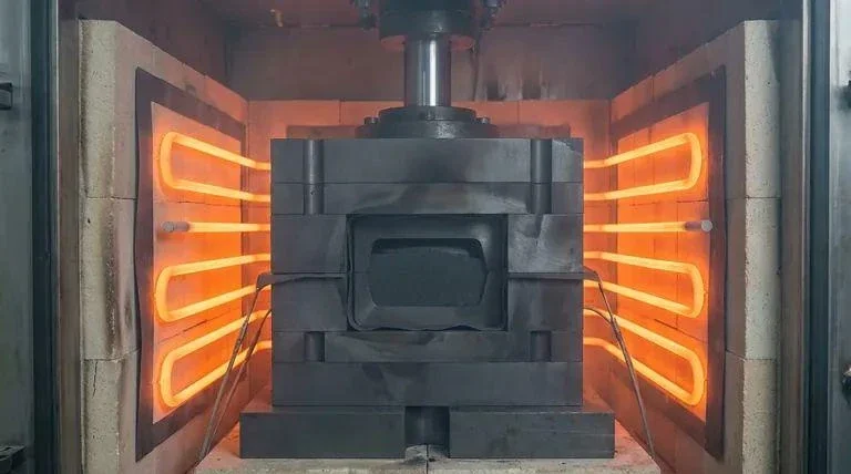
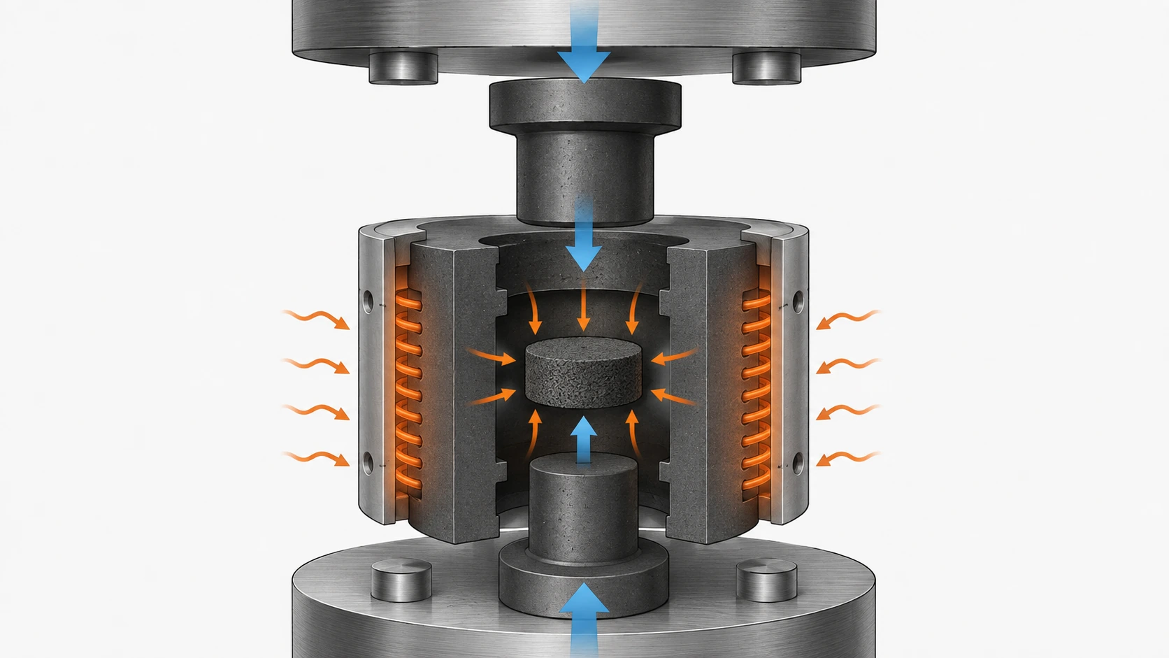
A graphite mold used for hot pressing or pressure-assisted sintering is part of the process, not just a container that survives high temperature. It carries mechanical load, conducts heat, contacts powder or a compact, moves through repeated heating and cooling cycles, and must still release a part with acceptable geometry and surface condition.
That makes the RFQ a process-definition exercise. Pressure history, temperature cycle, atmosphere, load path, contact surfaces, critical geometry, inspection requirements, and expected reuse all matter before a graphite grade can be selected sensibly. A material with impressive datasheet values can still fail if the mold geometry concentrates stress or if the furnace cycle exposes the part to conditions that were never considered in the drawing.
Start with the Process, Not the Graphite Grade
Four inputs establish the design boundary: mechanical loading, thermal history, atmosphere, and cycling. A nominal press capacity or maximum furnace temperature is not enough on its own.
For mechanical loading, identify how force reaches the graphite. Broad faces, thin walls, punches, inserts, shoulders, narrow bridges, and local contacts do not carry load in the same way. A mold that looks massive overall can still be controlled by one thin transition or small contact region.
Describe temperature as a cycle rather than a single peak value. Record the starting condition, ramp, soak, cooling sequence, and whether the mold remains loaded while temperature changes. Thermal gradients across thick and thin sections can matter as much as the nominal setpoint.
Atmosphere must also be explicit. Vacuum, inert gas, reducing conditions, process gas, and periods of air exposure create different risks. Loading, unloading, venting, leakage, and cooling practice can expose hot graphite to oxygen even when the main process is described as vacuum or inert.
Finally, distinguish a development tool from a production tool. A mold used for a few trials can justify a different inspection and replacement strategy from one expected to return to the same cycle hundreds of times.
- process type and material being pressed or sintered;
- press-force path and supported areas;
- temperature cycle and heating/cooling sequence;
- furnace atmosphere and air-exposure stages;
- expected cycle frequency and reuse plan;
- critical finished-part dimensions and contact surfaces;
- loading, unloading, cleaning, and handling method.
Choose the Grade Against the Load Path
Graphite grades are commonly compared by density, grain structure, strength, thermal properties, electrical properties, purity, and available blank size. Those values become useful only after they are tied to the mold’s actual job.
Thin walls, deep cavities, narrow bridges, small holes, threaded features, and replaceable inserts deserve more attention than a headline strength number. The key question is whether the selected material and geometry provide enough margin at the features that see the most demanding combination of stress, temperature, machining damage, and handling.
Thermal properties need the same context. Heat transfer through the mold depends on heater arrangement, graphite geometry, contact condition, insulation, furnace configuration, and workpiece placement. A thermal-conductivity value from a datasheet cannot predict the finished temperature field by itself.
For repeat supply, check that the grade is available in the required blank size and can be supplied consistently. If a qualified grade must be replaced, compare the property set that matters to the mold and then verify the new material in the actual process rather than substituting by density alone.
Density and Porosity Are Descriptors, Not Quality Scores
Density can support material control, but a higher number is not automatically better. Two grades with different density values can also differ in pore structure, strength, machinability, purity, thermal response, and directional behavior.
Porosity can influence machined surface appearance, residue retention, local edge behavior, cleaning response, and the way contact surfaces evolve in service. Those effects should be checked on the actual grade and feature geometry. Density by itself is not a release criterion for mold performance.
When density appears on an RFQ, state whether it is a nominal datasheet value, a guaranteed range, or a lot-release result. This prevents a typical marketing value from being treated as a contractual acceptance limit.
Control Surface Finish Where It Has a Function
Not every mold surface needs the same finish. A blanket low-Ra requirement can add machining and inspection cost without improving hot pressing or sintering.
Classify surfaces by function: workpiece contact, release, load transfer, locating, interface, and noncritical external faces. Apply tighter requirements only where surface condition affects release, transferred finish, dimensional stability, contact, or another defined process outcome.
If a roughness value is required, make the inspection basis practical. Measurement direction, access, graphite grain structure, and local pores can influence the result. Supplier and buyer should compare the same type of surface under a consistent method.
Reusable molds also need separate as-machined and in-service criteria. A contact face can accumulate polishing, residue, scratches, or local damage during cycling while remaining dimensionally acceptable elsewhere.
Geometry Often Controls the Failure
Graphite is highly machinable, but a machinable shape is not automatically a durable production shape. Sharp internal corners, abrupt section changes, thin walls attached to heavy sections, deep slots, and narrow bridges can concentrate mechanical or thermal stress.
Set radii and transitions from the local load path, machining access, section change, and workpiece geometry. The design review should identify which transitions are truly critical and whether they can be softened without changing the pressed part.
Replaceable inserts or wear features can improve tooling economics when one small region is expected to degrade before the main body. The joint itself still needs review for alignment, contact pressure, thermal expansion, contamination, and assembly risk.
Handling belongs in the same design review. A mold that is strong under a distributed press load may still be vulnerable to impact, leverage, or point loading during lifting, cleaning, storage, or assembly.
Inspect the Features That Decide Whether the Mold Can Run Again
There is no universal graphite cycle-life number for hot-press tooling. Service history belongs to the specific mold geometry and qualified process.
Inspection should focus on conditions that can end service: cracks, corner damage, distortion, dimensional drift at critical features, contact-surface damage, local oxidation, damaged threads or holes, and changes at replaceable interfaces.
During early qualification, frequent inspection helps reveal which features move first. Once the process is stable, the interval can be based on actual history instead of copying a generic cycle count from another tool.
Retirement criteria should be functional. A mark on a noncritical exterior face may be harmless, while a small crack at a loaded bridge or dimensional movement at a locating feature can justify removal. Photographs and selected dimensional trends are more useful than measuring every feature after every run.
Build the RFQ Around the Design Inputs
| Input | What to Define | Why It Matters |
|---|---|---|
| Process | Hot pressing, pressure-assisted sintering, or other defined operation | Establishes the mold’s actual function |
| Load | Force path, supports, punches, inserts, local contacts | Identifies mechanically critical features |
| Thermal cycle | Ramp, soak, cooling, and load timing | Frames thermal-gradient and cycling risks |
| Atmosphere | Vacuum, inert, reducing, process gas, and air-exposure stages | Defines oxidation and compatibility context |
| Workpiece | Material, powder/compact form, contact surfaces | Guides contamination and release discussion |
| Material | Approved graphite grade or required property set | Supports repeatable replacement supply |
| Geometry | Critical walls, corners, holes, slots, interfaces | Directs DFM and stress-concentration review |
| Surface | Function-critical contact and release faces | Avoids blanket over-specification |
| Inspection | Datums, critical dimensions, accessible measurements | Defines acceptance evidence |
| Reuse | Cleaning, inspection interval, retirement indicators | Supports controlled cycling |
What to Send QDZRT Graphite
For quotation and manufacturability review, send the 2D drawing or 3D model together with the process description. Identify the workpiece-contact faces, loading direction, furnace atmosphere, thermal cycle, critical tolerances, surface requirements, quantity, and whether the tool is for development or repeat production.
If a graphite grade has already been qualified, identify it and state whether the order requires exact replacement or an evaluated equivalent. If no grade is fixed, provide the application constraints rather than selecting material from density alone.
QDZRT Graphite can review blank size, machining approach, thin or fragile features, inspection access, and repeat-supply requirements. Final process qualification remains tied to the customer’s press, furnace, workpiece, and acceptance criteria.
Is higher-density graphite always better for a hot-pressing mold?
No. Density is one material descriptor. Grade selection also depends on structure, strength, thermal behavior, purity, feature geometry, machinability, stock size, and the actual load path.
Should every mold surface have a specified Ra value?
No. Apply a roughness requirement where surface texture performs a defined function, such as workpiece contact or release. Noncritical faces can usually follow normal machining requirements.
How should mold life be specified?
Use service history from the same qualified mold and process. Define inspection points, critical dimensions, damage indicators, and retirement criteria, then build the life expectation from actual production evidence.
For mold blanks where material direction can affect strength, expansion, or heat flow, use the graphite block anisotropy guide. For fine features and machined contact surfaces, the fine-grain graphite guide provides additional machining context.
References and Sources
- ASTM C651-20 — Flexural Strength of Manufactured Carbon and Graphite Articles Using Four-Point Loading at Room Temperature. Useful for room-temperature material characterization; it does not define allowable stress at hot-pressing temperature.
- ASTM D02.F0 — Manufactured Carbon and Graphite Products standards catalogue. Current catalogue includes material test methods used for controlled graphite property comparison.