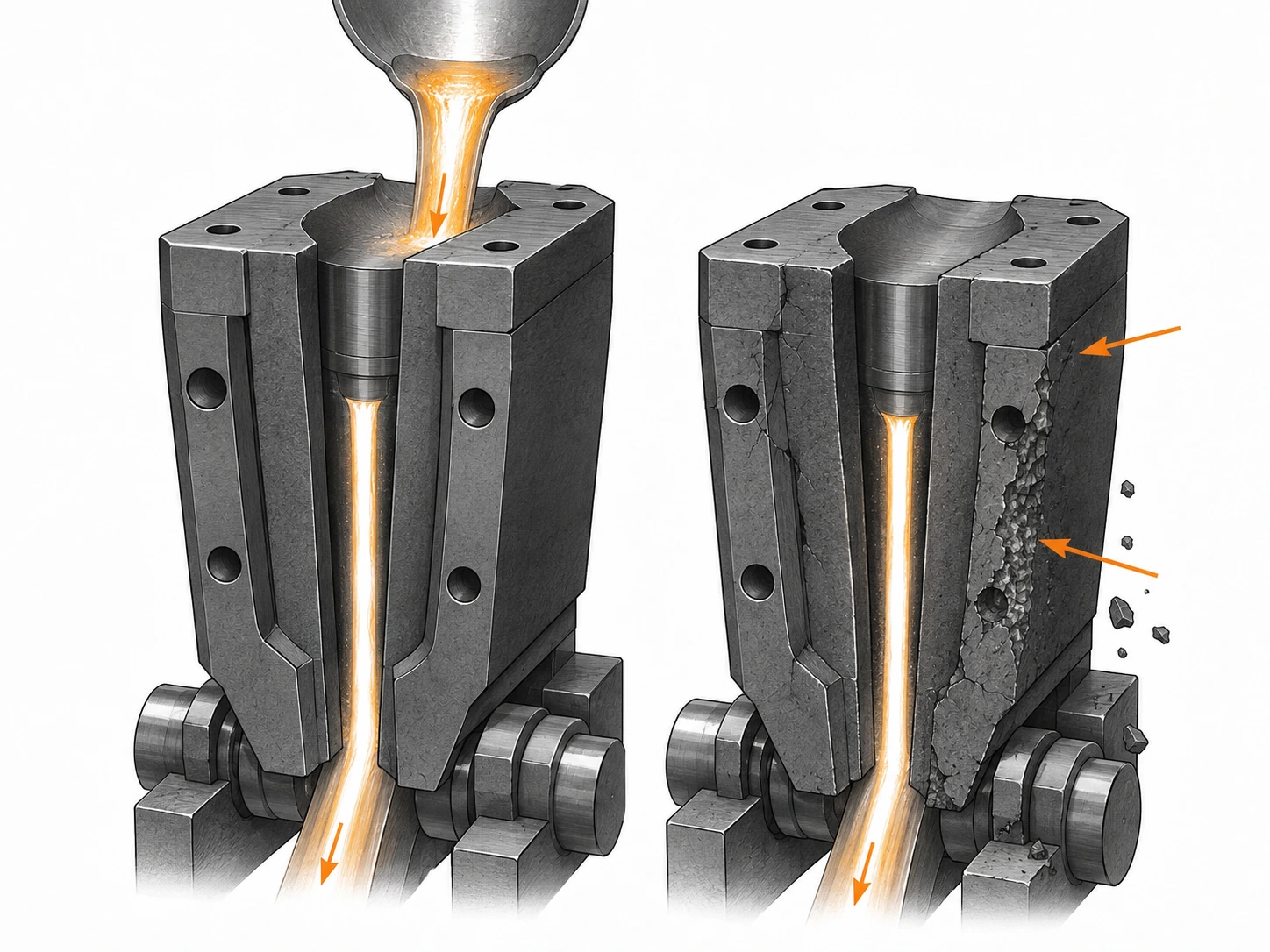
A continuous-casting graphite mold rarely reaches the end of service looking uniformly “worn out.” One mold may develop a polished or enlarged contact surface, another may show grooves or erosion near the metal path, another can crack after repeated thermal cycles, and another can keep running while the cast product slowly drifts out of dimensional control. Those are different failure modes and they should not all trigger the same response.
The useful selection method starts with the casting process: metal or alloy, casting direction, heat-extraction path, cooling arrangement, contact geometry, drawing speed or process regime, lubrication or protective practice where applicable, and the dimensional features that control the product. Material grade then supports that process. A graphite mold that works in one casting line cannot be assumed to deliver the same life in another simply because both lines cast metal continuously.
China’s current industry standard YB/T 4746-2019, Isostatic graphite for casting, provides a relevant product-standard framework for isostatic graphite used in casting molds. The standard covers grade designation, technical requirements, test methods, inspection, packaging, marking, storage, transportation, and quality certificates for this material category. It does not replace the casting-line drawing or provide a universal mold-life value.
Map the Metal, Casting Route, and Heat-Extraction Conditions
Graphite mold selection should begin with the specific metal, casting route, and heat-extraction conditions because those variables determine the thermal, chemical, and mechanical environment seen by the mold. A grade comparison without that process map is incomplete.

The metal or alloy changes contact chemistry, wetting behavior, solidification conditions, and the sensitivity to contamination. Record the actual alloy family and any process additives that contact the mold. If several alloys run through the same mold design, keep their service histories separate instead of averaging mold life across unlike campaigns.
Casting geometry matters. Rod, tube, strip, profile, or another cross-section creates a different contact perimeter and different regions where solidification and friction act on the mold. The location of the hot metal entrance, cooling zone, emerging solid, and any contact transition should be shown on a process sketch so failure locations can be compared with the thermal path.
Heat extraction is not represented by one furnace or metal temperature. Cooling-water arrangement, mold holder contact, external cooling, graphite wall thickness, local clearances, and the thermal conductivity of the actual grade all influence the temperature field. A local hot spot or an uneven cooling boundary can create distortion or thermal stress even when the nominal process settings remain unchanged.
For troubleshooting, preserve the process conditions associated with each removed mold: alloy, campaign, relevant speed or throughput state, cooling changes, start/stop events, abnormal interruptions, and reason for removal. The record does not need to expose proprietary production detail to every supplier; it needs enough information for the engineering team to identify whether failures cluster around a process change.
Material Grade and Property Priorities for the Mold
A continuous-casting mold grade should be screened by the properties that protect the actual heat-transfer, wear, dimensional, and structural requirements of the mold. No single density, grain-size, or strength number defines the best material.
Isostatic graphite is commonly considered for casting molds where uniform fine structure and lower directional variation are useful, and YB/T 4746-2019 provides an application-specific Chinese standard context. The buyer should still compare the supplier’s exact grade, stock size, density, relevant strength data, resistivity or thermal data where needed, purity, grain-size definition, and quality evidence.
Thermal conductivity matters because the mold participates in heat extraction, but a higher room-temperature value is not automatically better. The casting design may rely on a controlled thermal field, and conductivity changes with temperature. Compare data at relevant conditions where available and evaluate the finished process rather than ranking grades by one room-temperature number.
Strength helps the mold survive handling, clamping, thermal stress, and local loads, yet test method and direction matter. The graphite block anisotropy guide explains why directional property data should remain attached to the material axis. Do not convert a typical datasheet strength into a universal design allowable.
Grain size and pore structure can influence surface condition and local wear, but they also need definitions. The related fine-grain graphite guide shows why finer grain can support detailed surfaces without guaranteeing a fixed wear rate or service life.
| Mold concern | Material data to review | Do not reduce it to |
|---|---|---|
| Heat extraction | Thermal property data at relevant conditions and geometry. | One room-temperature conductivity value. |
| Cracking | Strength, thermal expansion, structure, orientation, thermal cycle. | Highest strength grade alone. |
| Wear/erosion | Microstructure, density/porosity, surface condition, alloy/process history. | Grain size alone. |
| Dimensional stability | Material response plus geometry, wear map, fixture and cooling. | Initial machining tolerance alone. |
| Contamination | Application-specific purity/chemistry evidence. | Generic total purity without sensitive elements. |
Geometry, Contact Surfaces, and Heat Flow
Mold geometry controls where heat and mechanical contact are concentrated, so a repeated failure at one location should trigger a geometry-and-process review before a blanket grade change. The mold is a heat-transfer component and a dimensional tool at the same time.
Wall thickness affects thermal path and mechanical section. A locally thin wall can run hotter or become mechanically vulnerable; a very thick section can change the heat gradient and add thermal mass. Abrupt transitions between thick and thin sections can create thermal-stress concentrations, especially during start-up and shutdown.
Internal corners, bore transitions, slots, coolant-related interfaces, mounting features, and sharp external corners deserve attention. Machining marks that run across a high-stress or high-wear area can also become initiation sites. The drawing should identify critical radii and surfaces rather than leaving the machine shop to choose every detail from convenience.
Contact surface finish is another controlled variable. A rougher surface can alter friction and product surface; an extremely smooth requirement may add machining cost without improving casting if the surface rapidly changes during run-in. Define the required finish and inspection method from qualified process evidence rather than from a generic graphite machining capability.
The holder or fixture is part of the heat path. Poor contact, debris, uneven clamping, or a distorted support can create local thermal differences and mechanical stresses. When only one mold position fails repeatedly, compare the holder and cooling system at that position before concluding that the graphite lot is defective.
Wear, Erosion, and Surface Damage
Wear, erosion, and surface damage should be mapped by location because each pattern suggests a different interaction between the cast metal, solidifying product, graphite surface, and process. “Bore worn” is not enough information to improve the next mold.
Measure the critical dimensions before use and after removal. A diameter or profile may enlarge uniformly, develop a local taper, become oval, or show grooves at one axial position. Those shapes contain more diagnostic information than a single maximum wear number.
Surface polishing can indicate repeated sliding contact. Grooves can point toward localized abrasion, entrained particles, hard inclusions, product contact, or a process alignment issue. Pits or rough areas may involve chemical interaction, local pullout, or thermal damage. The correct interpretation requires process and material evidence; visual appearance alone can be ambiguous.
Alignment should be checked when wear is one-sided. A misaligned casting path or holder can load one side of the mold more heavily. Changing to a harder or finer graphite can slow damage without removing the reason it is asymmetric.
Cleaning and refurbishment can create new surface damage. Scraping deposits, aggressive sanding, or uncontrolled reaming may alter dimensions and leave grooves that become the next wear path. Maintenance instructions should define which surfaces may be cleaned, re-machined, or polished and how dimensions are requalified afterward.
Thermal Shock, Cracking, and Dimensional Drift
Cracking and dimensional drift should be investigated through thermal-cycle history, crack location, fixture condition, and measured geometry. A cracked mold is not automatically evidence of low graphite strength.
Start-up and shutdown are often more informative than steady-state operation. A mold can experience rapid changes when hot metal first enters, cooling begins, flow stops unexpectedly, or a restart occurs before the system returns to a uniform condition. Record abnormal stops and cooling changes against the mold serial or lot record.
Crack origin matters. A crack beginning at a sharp corner or mounting feature suggests a different stress concentration from a crack crossing a uniform wall. A crack next to a region of heavy wear may indicate that section loss reduced the remaining mechanical margin. A crack associated with a damaged holder can point outside the graphite entirely.
Dimensional drift may occur without an obvious crack. Wear, local oxidation where air enters, surface erosion, deposit buildup, fixture movement, or repeated maintenance can change the effective mold geometry. Product dimensions can therefore drift even while the mold appears visually usable.
Trend the product and mold together. If product diameter or profile begins moving toward a control limit, inspect the corresponding mold dimension before waiting for a gross defect. Planned removal based on dimensional trend can be cheaper than running to a fracture or producing a large quantity of out-of-tolerance product.
Inspection and Refurbishment Decisions
A mold should be removed, refurbished, or scrapped according to controlled dimensional and defect criteria, not only an operator’s visual impression. Refurbishment is justified when enough sound material remains to restore the critical geometry without creating a new weakness.
Incoming inspection establishes the baseline: grade identity, dimensions, critical surface condition, visible chips or cracks, and certificate data. Record the starting measurements that will later be used to calculate wear. A mold without a baseline is harder to diagnose after service.
In-service or between-campaign inspection can focus on the dimensions and surfaces known to drive product quality. The frequency should follow the process risk and accumulated history rather than a universal number of casting hours. A stable process may justify wider intervals; a new design or known failure trend may require closer monitoring.
For refurbishment, define the maximum material removal and the geometry that must remain after re-machining. Removing a worn layer can restore surface finish while also thinning the wall or changing the heat path. The engineering owner should approve the final refurbished geometry.
Keep refurbished molds identifiable. A mold on its second or third machining cycle should not be mixed with a new mold if the remaining wall section or service expectation differs. Traceability allows the team to compare whether refurbishment is economically extending life or only postponing replacement by a short interval.
Second-source qualification should preserve the failure map as well. A replacement grade may match the original density and strength yet wear differently at the metal contact surface or change the thermal field enough to shift product dimensions. Run the new material through a controlled campaign and compare the same mold measurements, product-quality indicators, and removal criteria. A supplier equivalency decision based only on the incoming datasheet misses the reason the mold exists.
Stock orientation and machining history can also affect troubleshooting. If the mold is cut from a large block, record the parent block and blank orientation when the grade has directional data. Record major machining operations and any repaired surface. When two nominally identical molds behave differently, those manufacturing records provide variables that are otherwise lost after installation.
Packaging deserves a place in the failure record for large or thin molds. Edge chips, concealed cracks, or fixture damage created during transport can grow during the first thermal cycle and be misclassified as a casting failure. Photograph the mold at receiving and after installation for high-value programs. If damage occurs before service, correct the packaging or lifting method instead of changing the graphite grade.
Translate Failure History into the Next Mold Specification
The next mold specification should change only the variables supported by the failure evidence. A good failure record converts wear and damage into drawing, material, process, inspection, or maintenance actions.
Use a failure-history table with columns for mold ID, graphite grade and lot, drawing revision, alloy/campaign, start and stop dates, key process changes, reason for removal, wear map, crack location, dimensional results, refurbishment history, and final disposition. Add photographs tied to the same ID.
Then classify the action:
- Material action: change grade or property requirement when evidence points to material structure, purity, strength, or thermal behavior.
- Geometry action: change radius, wall section, contact surface, or mounting feature when failures repeat at a design concentration.
- Process action: adjust start-up, cooling, alignment, lubrication/protection, or casting conditions when failures track the process.
- Inspection action: add a measurement or earlier removal threshold when dimensional drift is detected too late.
- Maintenance action: control cleaning or refurbishment when damage is introduced after casting.
YB/T 4746-2019 can support the material purchase framework for casting-use isostatic graphite, but the actual mold RFQ should add the controlled drawing, relevant property evidence, inspection requirements, marking/traceability, packaging, and change notification needed by the casting operation.
The objective is not to maximize mold life at any cost. A mold that lasts longer but transfers heat differently, produces worse dimensional control, requires scarce stock, or takes much longer to machine may not reduce total casting cost. Compare accepted production, downtime, mold cost, refurbishment, scrap, and process stability together.
Failure history is therefore part of the specification. Every removed mold should make the next purchase more informed. When wear, cracking, erosion, and dimensional drift are kept as separate signals, the team can change the right variable instead of writing “use better graphite” on the next RFQ.
When the process changes intentionally, start a new comparison baseline. A higher casting rate, new alloy, revised cooling arrangement, modified mold holder, or new product tolerance can change the wear mechanism even though the graphite grade is unchanged. Mixing pre-change and post-change service-life data hides that effect. Version the process condition together with the mold drawing so engineering can tell whether a life change came from material, geometry, or the casting system. That separation is essential when supplier changes and process upgrades happen during the same production period and the team must assign the correct engineering corrective action confidently later.