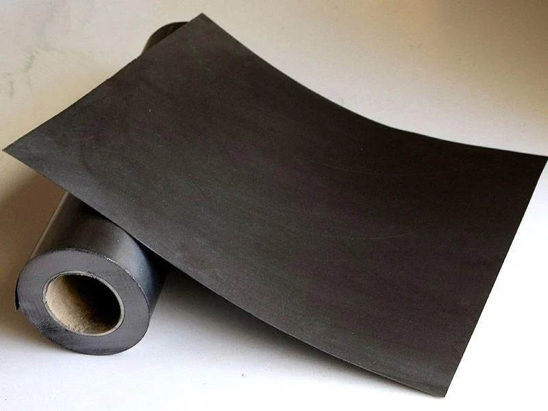
Reinforced graphite sheet should be specified by its laminate architecture, not by the word “reinforced” alone. A smooth metal-foil insert and a tanged insert both add reinforcement to flexible graphite, but they create different internal structures. Those structures affect how the graphite layers are supported, how the laminate is cut, what the edge looks like after conversion, and how the converter should describe the material on an RFQ.
China’s standard system distinguishes flexible graphite sheet and reinforced graphite gasket constructions. JB/T 6613-2008, Flexible graphite sheets and strips—Classification, designation and marking, is a current industry reference for flexible graphite sheet/strip classification and marking. JB/T 6628-2016, Flexible graphite composite reinforced (sheet) gaskets, is a current industry reference for reinforced flexible graphite gasket products. These references help define product families, but they do not mean every converter should use the same reinforcement structure for every service.
The broader flexible graphite sheet selection guide covers material choice for gasket manufacturing. This article stays narrower: foil insert versus tanged insert as a laminate-structure and conversion decision.
Start with the Reinforcement Architecture
The reinforcement architecture determines how the metal insert and flexible graphite layers share load, resist handling damage, and remain connected during cutting and gasket conversion.
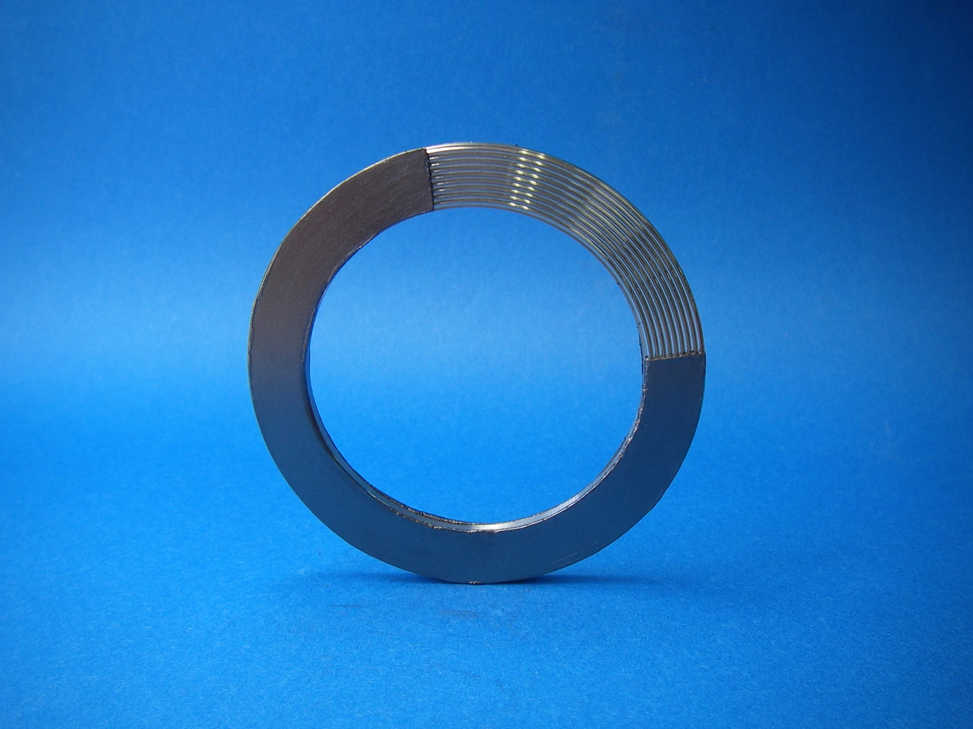
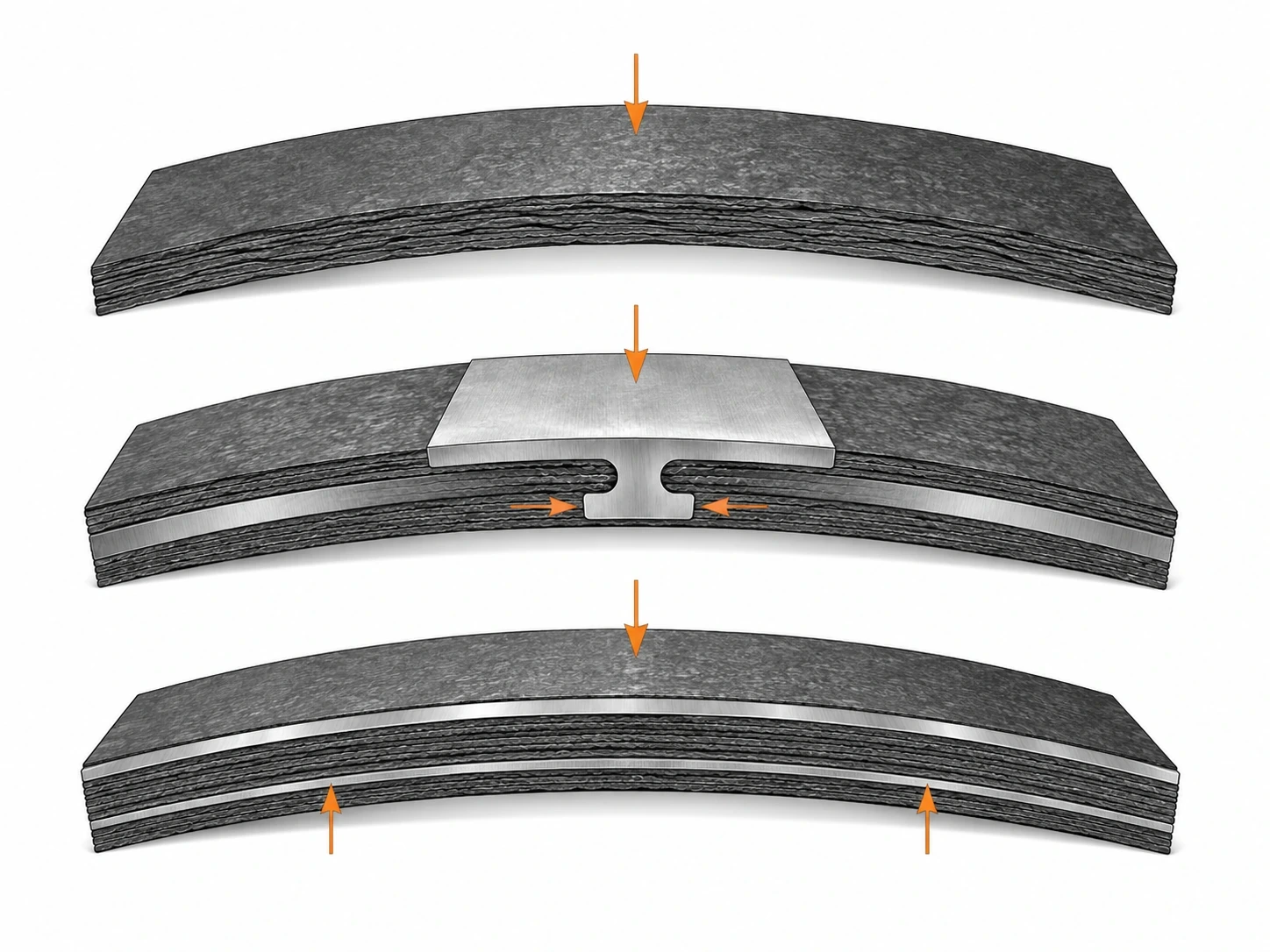
A reinforced sheet is a laminate rather than a homogeneous graphite slab. Flexible graphite provides the compressible sealing material; the metal insert provides structural support. The way those layers are joined creates the main difference between foil-insert and tanged-insert constructions.
In a smooth foil construction, the metal reinforcement remains substantially continuous and the graphite layers are bonded to or laminated around it. In a tanged construction, the metal insert is mechanically formed so portions of the metal penetrate or engage the graphite layer, creating a physical interlock in addition to the laminate structure.
That difference affects the converter before the gasket ever sees service. Cutting tools encounter a different metal geometry. Edge appearance changes. The sheet can behave differently during lifting, feeding, stripping, and handling after die cutting. The choice depends on both the converter’s manufacturing route and the gasket’s service requirement.
Note: “Reinforced graphite sheet” is not a complete purchase description. The RFQ should state the reinforcement form, metal type where required, nominal sheet construction, and the properties that the converter has actually qualified.
Foil Insert: How the Laminate Is Built
A foil-insert reinforced graphite sheet uses a relatively continuous metal foil layer inside the graphite laminate, giving the converter a smooth reinforcement plane rather than a mechanically pierced interlock.
The continuous foil can provide handling support across the sheet area and can help the converted gasket maintain integrity during cutting and installation. Because the insert is not formed into numerous tangs, the local graphite structure around the reinforcement remains different from a tanged laminate.
For cutting, the tool must pass through graphite and a continuous metal layer. The metal thickness, hardness, tool condition, die clearance, cutting direction, and part geometry can all influence edge burr, distortion, and tool wear. A converter should qualify the actual laminate instead of assuming that two foil-insert products with the same overall sheet thickness will cut identically.
Bond quality also matters. A smooth foil does not create the same mechanical interlock as a tanged insert, so the laminate depends on the manufacturing construction used to keep the graphite and reinforcement integrated. Incoming inspection should therefore include the edge and surface condition, not only overall thickness.
Foil construction can be useful when the converter wants a relatively clean internal reinforcement layer or when the qualified gasket design is based on that architecture. It should not be selected merely because “smooth sounds better.” The service and conversion evidence must support the choice.
Tanged Insert: How Mechanical Interlocking Changes the Sheet
A tanged insert changes the laminate by using formed metal features that mechanically engage the flexible graphite, creating a reinforced structure with localized metal penetration into the graphite layer.
This interlock can improve resistance to layer separation during handling and conversion, but it also creates a more complex internal geometry. The graphite is not simply resting against a smooth foil; it is formed around the metal tangs. That difference is visible at cut edges and can affect tool load, edge finish, and the way thin gasket features behave.
The tang geometry should remain part of the qualified construction even if the buyer does not specify every manufacturing detail. A major change in insert pattern, metal thickness, or reinforcement route can change conversion behavior. The RFQ can therefore identify the tanged construction and require change notification without demanding proprietary tooling drawings.
For small holes, narrow bridges, thin gasket lands, or intricate profiles, the converter should test whether the tanged structure leaves acceptable edge integrity after cutting. Minimum feature size has to be established on the actual laminate, tooling, and gasket geometry; the article does not assign a generic number.
Caution: Do not assume “tanged” automatically means stronger in every converted gasket geometry. The local metal pattern that improves laminate interlock can also make some fine features more difficult to cut cleanly.
Compare Handling, Cutting, and Edge Behavior
Handling, cutting, and edge behavior should be compared on the converter’s actual equipment because reinforcement architecture changes the way the sheet resists bending, stripping, tool penetration, and local edge damage.
During sheet handling, observe whether the laminate cracks, delaminates, creases, or sheds graphite at corners and edges. During cutting, record tool type, die or knife condition, feed direction, part nesting, and the defects that appear. During part removal, check whether narrow features distort or layers separate.
| Converter question | Foil insert | Tanged insert |
|---|---|---|
| Internal reinforcement plane | Relatively continuous smooth foil | Mechanically formed insert with tang engagement |
| Edge after cutting | Shows graphite layers plus continuous metal cut | Can show local formed-metal features in the edge region |
| Tool interaction | Continuous metal layer must be cut | Tool encounters formed insert geometry and graphite interlock |
| Laminate integrity check | Focus on bond/laminate condition and edge separation | Focus on interlock condition, edge tearing, and local metal pull |
| Best comparison method | Cut the real gasket geometry using the qualified converter process and inspect the resulting part. | |
Do not judge conversion only by whether the part can be cut once. Repeatability matters. A material that produces clean parts at the start of a run but rapidly increases tool wear or edge defects may create a higher conversion cost. Conversely, a sheet that feels stiffer during handling may reduce breakage or make automated feeding easier.
Scrap behavior can also differ. The way internal reinforcement remains attached to graphite affects how waste strips, punched centers, and narrow offcuts behave during removal. This can influence operator time and process cleanliness even if the finished gasket itself is acceptable.
Compare Sealing-Service Considerations Without Mixing Gasket Designs
Evaluate sealing service within the complete gasket and flange system. Reinforcement architecture alone cannot predict leakage, temperature capability, or pressure capability.
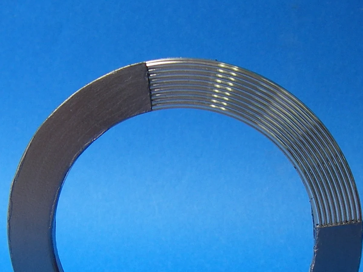
The flexible graphite layer still provides the principal conformable sealing medium, while reinforcement affects mechanical support and structural handling. Service behavior also depends on gasket thickness, density, reinforcement material, flange condition, gasket stress, surface finish, medium, temperature, pressure, thermal cycling, oxidation environment, and installation.
That means a foil-insert sheet that performs well in one gasket design cannot be ranked universally against a tanged sheet used in another design. The converter should compare the two structures using the same gasket geometry and service-relevant test plan when the objective is a direct substitution.
Metal compatibility also matters. Stainless steel and other reinforcement materials are selected for different chemical, temperature, corrosion, and fabrication requirements. The buyer should specify the reinforcement metal where the application or customer standard requires it rather than leaving the supplier to choose by habit.
The existing graphite sealing in flanges, valve stems, and pump shafts guide explains why sealing jobs differ by load and movement. For reinforced sheet used to make gaskets, the reinforcement choice should remain tied to the static gasket design instead of being generalized to all graphite sealing forms.
Choose the Structure by Converter and Service Requirements
The correct reinforcement structure is the one that the converter can process reliably and that the finished gasket can use within the defined service system. A defensible choice combines conversion evidence with service evidence; the label “stronger” is too vague to make the decision.
Start with the converter’s failure history rather than with a preferred reinforcement label. If current scrap is driven by edge separation, layer lift during stripping, or handling damage, the qualification should emphasize laminate integrity. If scrap is driven by burr-like metal exposure, damaged narrow lands, difficult punching, or accelerated tool wear, the qualification should emphasize cut-edge quality and tooling interaction. This converts the material choice into a measurable production problem instead of a generic foil-versus-tanged preference.
Next freeze the variables that must not move during the comparison: graphite grade or qualified material family, overall thickness, density basis, reinforcement metal, gasket geometry, cutting method, tool condition, and inspection rule. If those variables change together with the insert architecture, the trial cannot show whether the observed difference came from foil versus tanged reinforcement or from another material/process change.
| Qualification gate | Evidence to collect | Decision question |
|---|---|---|
| Incoming laminate | Construction identity, thickness, surface/edge condition, lot traceability | Did the candidate arrive in the intended architecture and condition? |
| Conversion | Representative holes, narrow lands, large rings, scrap stripping, tool condition | Can the real product geometry be cut repeatedly without new defect modes? |
| Edge integrity | Approved-edge photographs or retained samples from the same inspection basis | Does the converted edge remain inside the accepted functional condition? |
| Handling | Feeding, lifting, part removal, stacking and automated-transfer observations | Does the laminate stay intact through the actual production route? |
| Gasket qualification | Finished-gasket evidence under the buyer’s service-relevant test plan | Does the converted part remain acceptable in the intended joint? |
For a second-source or architecture substitution, require the candidate to pass the gates in order. A sheet that seals acceptably but causes unacceptable conversion scrap is not operationally equivalent. A sheet that cuts cleanly but changes the qualified gasket result is not functionally equivalent. Keeping conversion and service evidence separate is the strongest way to prevent one successful test from hiding a failure in the other half of the supply chain.
Example: A converter choosing between foil and tanged reinforcement should compare sheet handling → tool interaction → cut-edge integrity → part removal → gasket qualification. If both structures pass service requirements, conversion yield and repeatability may become the deciding factors.
Receiving inspection should mirror the converter’s risks. For a qualified reinforced sheet, inspection can include lot identity, overall thickness, surface condition, obvious laminate separation, reinforcement identity where visible or documented, and representative conversion checks where the process is sensitive. Do not invent destructive inspections for every shipment if they are not connected to a known failure mode.
Storage and handling should also preserve the laminate. Large sheets can be damaged by bending, edge impact, moisture exposure in unsuitable packaging, or poor stacking. If the converter receives a visually damaged sheet, the defect may be logistical rather than a material-design failure. Packaging requirements therefore belong in the RFQ when handling damage has been observed.
For repeat supply, save photographs or retained cut samples of the approved edge condition and link them to the laminate construction, production lot, tool or die family, and representative gasket geometry. When a later lot cuts differently, the converter can compare the same defect mode on the same basis instead of relying on descriptions such as “the new material feels different.” This is particularly useful when the reported thickness and graphite grade still look unchanged.
Write the Reinforcement Structure into the RFQ
The RFQ should describe the reinforced graphite sheet in enough detail that the supplier cannot substitute a different internal architecture while keeping the same overall thickness and graphite description.
At minimum, define whether the insert is smooth foil or tanged, the reinforcement metal where required, overall sheet thickness, graphite density or other material field where qualified, sheet size, surface/edge quality expectations, and the documentation needed for repeat supply. If a customer or gasket standard controls the construction, reference that requirement.
Also define whether a sample or converter trial is required before production. For a new source, the buyer should cut representative gasket geometries rather than only measure sheet thickness. If small features or automated processing are sensitive, include them in the qualification sample plan.
Change control should cover the reinforcement architecture. A supplier should notify the buyer before changing foil type, tanged construction, reinforcement metal, or another critical laminate feature that could alter conversion or service. The buyer can then decide whether documentation review, sample confirmation, or requalification is needed.
A practical RFQ field set is:
- Flexible graphite reinforced sheet construction: foil insert or tanged insert.
- Reinforcement metal and material requirement where applicable.
- Overall thickness and qualified graphite density/grade fields.
- Sheet dimensions and tolerance basis.
- Surface, edge, lamination, and visible-defect expectations.
- Lot identity and test documentation.
- Sample requirement for gasket-conversion trial.
- Change-notification rules for reinforcement architecture.
For QDZRT Graphite, a useful inquiry includes the intended gasket type, sheet construction, reinforcement metal, thickness, density or existing reference material, drawing or representative gasket geometry, expected order format, and the conversion problem being solved. That information makes it possible to discuss the laminate as a manufacturing material instead of quoting an undefined “reinforced graphite sheet.”
The central decision is structural: smooth foil and tanged inserts solve reinforcement in different ways. The buyer should preserve that difference in the RFQ, qualify the conversion behavior, and then confirm the gasket within the real service design.
Keep the approved structure tied to the converter trial, the material lot, and the final gasket drawing. That three-way traceability makes later supplier changes and defect investigations much easier to control.
Qualification coupons should include the difficult production features that actually drive scrap, not only simple rectangles. A laminate may cut cleanly in a straight strip while showing different behavior around bolt holes, narrow webs, sharp internal corners, or large-diameter rings. Those features concentrate tool interaction and can expose the difference between a continuous foil layer and a tanged reinforcement. The sample plan should therefore include the features that drive real scrap and handling risk in the converter’s product mix.
Inspection of the finished edge should also be tied to function. A visually rough cut is not automatically unacceptable if the gasket geometry and service qualification remain sound, while a small local separation can be important if it propagates during handling. Establish acceptance examples from approved parts rather than relying on vague language such as “clean edge.” Photographs, retained samples, or a simple defect reference can make supplier and converter judgments much more consistent.
For automated conversion, qualify feeding and part removal as well as cutting. Reinforcement architecture can change stiffness and scrap behavior in ways that are not visible from a static sheet inspection.
For repeat conversion, keep the approved laminate construction tied to the converting setup: tool or die family, feed direction, representative part geometry, and the defect examples used at incoming inspection. When any of those conditions changes, compare edge condition, delamination, handling damage, and scrap on the same representative shapes before assuming the previous acceptance window still applies.