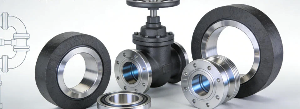
Graphite sealing materials work in static flange joints, moving valve stems and rotating pump assemblies. The material family may be similar, but the load is not. A flange gasket receives bolt compression across a broad area. Valve packing seals around a moving stem. Pump packing must control leakage while a shaft passes under it every revolution.
QDZRT Graphite supplies graphite sealing materials in sheet, gasket and ring forms, including flexible graphite sheet for high-temperature systems. The order starts with the sealing position. Dimensions come next. Pressure and temperature then narrow the material form.
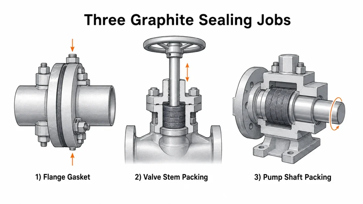
Three Places Graphite Seals
A pipe flange is static after assembly, but its load still changes. The gasket settles during tightening. Bolts expand as temperature rises. Connected piping can rotate the joint or unload one side. A gasket installed at 20 °C may later operate at 350 °C, while the line moves several millimetres between those conditions, so a “static” joint still needs a controlled seating load, a known face finish and a documented tightening procedure.
A valve stem creates a different problem. Five to seven rings sit in many stuffing boxes. The gland compresses the stack, and the rings push inward against a stem that travels or turns. Small valves may use 20–35 mm stems. Process valves can reach 50–100 mm. Sealing load must remain below the actuator’s available thrust, and the packing arrangement has to suit the motion pattern, stem condition and service atmosphere.
A pump shaft adds continuous sliding speed. A 40 mm sleeve at 1450 rpm runs near 3.0 m/s. At 2900 rpm it reaches about 6.1 m/s. An 80 mm sleeve at 2900 rpm is close to 12.1 m/s. That difference changes frictional heat and the need for cooling, which is why pump packing must be reviewed together with leakage allowance, lubrication and flush arrangements.
| Sealing position | Common graphite form | Required project inputs | Illustrative screening note |
|---|---|---|---|
| Raised-face flange | Plain or reinforced graphite gasket | Flange standard, pressure class, nominal size, facing type, gasket thickness, service temperature and approved gasket grade | An early RFQ may mention PN 10–PN 40 or ASME Class 150–300 with 1.0–3.0 mm thickness as an illustrative project example, but the approved gasket data and joint calculation remain controlling. |
| Higher-load or hotter flange | Reinforced graphite gasket | Facing finish, bolt materials, operating temperature profile, gasket reinforcement requirement and approved installation procedure | A buyer may describe Class 300–600 service or a thicker construction during screening, but every higher-load case still requires grade-specific gasket data and a joint-specific tightening method. |
| Valve stem | Die-formed graphite packing rings or packing set | Stem diameter, stuffing-box bore and depth, ring count, section size, gland-stud size, stem motion and packing-box temperature | Typical enquiry notes may mention 20–100 mm stems with 5–7 rings and 6–12 mm sections, but final packing dimensions and loading limits must follow the valve OEM or approved packing procedure. |
| Pump stuffing box | Braided graphite packing or formed ring set | Sleeve diameter, rpm, calculated surface speed, box depth, ring arrangement, flush connection, pumped medium and temperature | A screening note may describe 25–100 mm sleeves or 4–6 rings, but flush pressure, leakage control and temperature limits are equipment- and packing-specific. |
Similar graphite material families may appear across the three applications, but the gasket or packing construction, grade and dimensions remain application-specific. A flange needs a face dimension and a bolt pattern. A valve needs a stem diameter and a box bore. A pump needs a sleeve diameter and a rotational speed. The ordering logic therefore starts from the sealing position, not from the assumption that one ring or one generic grade can be moved from one location to another.
These tables and numeric notes are an RFQ screening framework, not universal ratings. Pressure class describes the flange system. Gland torque depends on stud size, packing arrangement and lubrication. Pump cooling follows the equipment procedure. Final limits come from the approved product data, the machine design and the service atmosphere.
Flange Gaskets
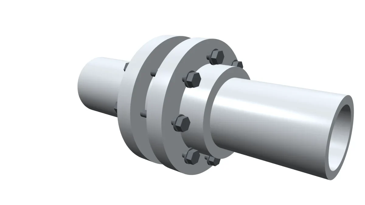
A graphite gasket needs enough initial stress to conform to the faces, then enough retained stress to resist pressure after relaxation. One project may review 35–70 MPa as an illustrative initial seating-stress band and 20–35 MPa as a retained-stress checkpoint, but those values only become meaningful when tied to the approved gasket data, flange geometry and the pressure-design method used for that joint.
PN 10, PN 16, PN 25 and PN 40 identify nominal flange systems. ASME Class 150, Class 300 and Class 600 use another rating system. Allowable pressure changes with flange material and temperature. “Class 300” therefore does not mean a fixed 300 psi limit, and it must never be treated as a direct substitute for gasket seating stress.
Thickness changes relaxation. A 1.0 mm gasket demands flatter faces. A 1.5–2.0 mm gasket is a practical middle range for many rigid joints. A 3.0 mm gasket absorbs more local irregularity but needs better bolt-load control. A 4.5 mm construction belongs only where the flange geometry and reinforcement support it. These thickness examples help an enquiry start, but the approved construction still has to match the facing style and load capability of the real joint.
Surface finish also needs a documented basis. A serrated raised face around 3.2–6.3 µm Ra is often reviewed because flexible graphite can conform into that texture. Below about 1.6 µm Ra, some joints lose mechanical grip. Above about 12.5 µm Ra, the grooves may be too deep for a thin gasket. Those ranges should be checked against the approved gasket data sheet and the specific flange standard instead of being copied as a universal acceptance rule.
Gasket area sets total bolt-force demand. An effective area of 10,000 mm² at 40 MPa needs about 400 kN before losses. Increasing the area to 20,000 mm² raises that force to about 800 kN. A wide custom annulus therefore cannot be approved from thickness alone; the calculation has to consider the full loaded area, the bolt set and the flange stiffness.
Plain graphite fits many cover joints. Reinforced graphite improves handling and resistance to blowout. The article on choosing flexible graphite sheet for high-temperature gaskets explains sheet construction. Flexible graphite versus PTFE gaskets compares temperature capability with creep behaviour.
A staged tightening sequence such as 30%, then 60%, then 100% of the approved torque may appear in an OEM or plant procedure, followed by a circular verification pass. The exact sequence and N·m value still come from bolt diameter, lubricant condition and the approved joint method. OSHA’s process-safety guidance supports the need for controlled installation quality, including uniform torque on flange bolts and proper pump-seal installation, but it should not be read as a source for one fixed percentage sequence.
Valve Stem Packing
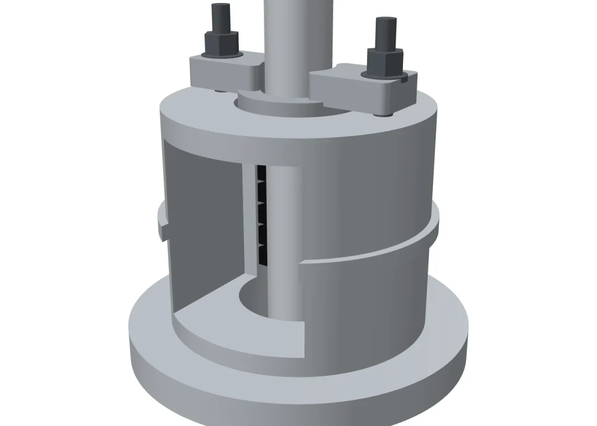
Valve packing balances leakage against friction. Gland load compresses the rings axially. Part of that load becomes radial pressure on the stem. Too little compression leaks. Too much raises actuator demand. The packing set therefore has to be evaluated together with stem finish, box geometry, gland hardware and the motion pattern expected in service.
A typical graphite set contains 5–7 rings. Common square sections include 6 mm, 8 mm, 10 mm and 12 mm. A 50 mm stem inside a 70 mm box gives a nominal 10 mm radial space, so a 10 mm ring is the geometric starting point. Box depth then decides whether 5 rings or 6 rings fit after seating, and whether end rings, braided corner rings or spacers are required.
Stem diameter changes sensitivity. On a 20–35 mm stem, a 0.2 mm mismatch consumes a large share of the clearance. A 50–100 mm stem places more area under contact, so friction rises quickly with gland load. Surface finish around 0.4–0.8 µm Ra may be used as a review range, and runout above roughly 0.05–0.10 mm deserves equipment inspection, but both values still have to be checked against the approved packing design and the valve OEM condition.
Packing cannot repair a damaged stem, sleeve or stuffing-box surface. We confirm the hardware condition and the approved packing arrangement before treating leakage as a material issue.
Gland torque must match the specific bolt size, stud lubrication, and packing set design. Gland adjustments should follow staged increments per the valve manufacturer’s procedure or packing supplier torque table, monitoring gland follower squareness, stem friction, and travel until leak tightness is achieved. Final tightening parameters must be verified against approved engineering procedures and site commissioning records.
For continuous oxidizing service, 450 °C is a sensible screening ceiling for many flexible-graphite packing discussions. Steam or inert service may permit 600–650 °C, but the complete packing set, oxidation resistance and valve structure must support it. The temperature at the packing box may be lower than the process temperature; both values are useful, and both should be reported when a packing grade is being selected.
Where the equipment procedure permits, cycle the valve through several full strokes before the final leakage check and adjust the gland by equal movements on both nuts. An official valve-packing manual available through OSTI discusses leakage versus operating force and reports 0.18–0.33 mm clearances for one test configuration. Those figures describe that specific test arrangement; they are not a universal stem or packing-box rule. Final ring dimensions still come from the stem, box bore and installed depth.
Pump Shaft Sealing
A pump shaft adds surface speed. A 40 mm sleeve produces about 3.0 m/s at 1450 rpm, 6.1 m/s at 2900 rpm and 7.5 m/s at 3600 rpm. At 80 mm diameter, those values rise to approximately 6.1 m/s, 12.1 m/s and 15.1 m/s. Surface speed is therefore a required enquiry field rather than a detail to estimate after the packing has already been chosen.
The surface-speed calculation helps separate low-, medium- and higher-duty cases, but the cooling requirement still depends on pump type, packing construction, medium, leakage allowance and OEM procedure. A project may observe gland temperature carefully during the first 15–60 min or may specify a lantern-ring flush with a pressure margin above the box pressure, yet both settings remain equipment-specific rather than universal operating rules.
Around 260 °C can be used as a conservative screening ceiling for some continuous rotating duties with a lubricated graphite packing set unless complete packing data permits more. Some systems may reach 300 °C. The 450 °C figure used for slower or more static graphite-service discussions must not be copied directly into a high-speed pump because frictional heat, lubrication stability and shaft condition become controlling limits.
A 0.05 mm shaft runout changes the radial gap every revolution. At 2900 rpm, the packing experiences that cycle 2900 times each minute. A 0.4–0.8 µm Ra sleeve can reduce cutting action, but a scored or misaligned sleeve can still damage a new ring set before gland adjustment stabilizes. Pump duty therefore combines speed, surface condition and cooling into one practical release decision.
A stuffing box may contain 4–6 rings and a lantern ring. With a 10 mm compressed ring height, moving the lantern ring by one position shifts it about 10 mm and can block the flush port. The order needs the complete axial arrangement, including whether flush enters through a lantern ring, a quench line or another local design feature.
Zero visible leakage is not always the correct target for compression packing. Closing the gland until dry can remove the cooling film and raise motor load. The approved pump procedure decides whether controlled leakage, external flush or a mechanical seal is required. Our team can discuss graphite sheet and formed-ring supply, but the complete pump sealing set remains equipment-specific.
Why the Same Material Behaves Differently in Each
A flange may complete one pressure hold after a 100% torque pass and remain static for months. An isolation valve may see 10 strokes per year, while a control valve exceeds 1000 strokes. A pump at 2900 rpm completes more than 4 million revolutions in 24 h. Similar graphite chemistry does not create similar mechanical duty, which is why movement changes the failure mode and the acceptable sealing strategy.
| Application | Primary motion or load pattern | Control variable to review | Project input to record | Commissioning or verification note |
|---|---|---|---|---|
| Flange gasket | Static after assembly, then relaxation under temperature and piping load | Seating stress, retained load and face finish | Flange class, facing type, gasket thickness, effective area and approved gasket grade | Confirm the approved tightening method and pressure hold requirement for that joint. |
| Valve stem packing | Intermittent rising, reciprocating or rotating stem motion | Gland load versus leakage and operating force | Stem diameter, box bore and depth, section size, ring count, stud size and box temperature | Use the valve or packing procedure to set trial tightening, cycling and leakage checks. |
| Pump shaft packing | Continuous rotation with speed-dependent frictional heat | Surface speed, leakage allowance, cooling and shaft condition | Sleeve diameter, rpm, calculated m/s, medium, temperature, flush arrangement and ring layout | Run the approved start-up check for temperature, leakage and flush performance. |
A flange gasket receives its full bolt load once and then relaxes toward a retained-load condition. Valve packing is re-loaded every time the gland is adjusted, so its stress record becomes a series of steps instead of one settling curve. Pump packing loses and regains its lubricating film continuously, which is why a running observation often reveals more about it than any single torque figure. Similar graphite chemistry can therefore fail for three unrelated reasons if the position-specific duty is ignored.
The medium also reaches each seal differently. A flange exposes the bore edge. Valve packing receives pressure at the process end. Pump packing is wetted continuously and may trap abrasive particles against the sleeve. “Steam service” or “acid service” is not enough information to release one form for all three positions.
Installation Details That Decide Leakage
For a flange, record face finish and gasket thickness. Confirm alignment before the bolts pull the joint together. Centre the gasket. Lubricate threads only when the approved torque calculation assumes that lubricant.
For valve packing, measure the stem at several axial positions and at 4 angles. Seat each ring separately. Keep the gland follower parallel; a 1 mm height difference indicates uneven compression. Tighten in equal increments, then cycle the valve and record leakage.
For pump packing, verify shaft runout. Confirm lantern-ring position after compression. Start with enough allowance for cooling, then adjust in equal movements while observing temperature during start-up. A rapid temperature rise calls for inspection, not harder tightening.
Record what was measured, not only what was fitted. A flange record holds the face finish and the final torque pass. A valve record holds ring count, section size and the gland reading at which leakage stopped. A pump record holds sleeve runout and the lantern-ring position confirmed after compression. Those entries turn the next replacement into a repeat of a known condition.
Cold installation is only the first condition. Some flange procedures allow hot retorque; others prohibit adjustment under pressure. Some pumps require continuous flush. The applicable equipment procedure and plant safety rules control those actions.
Ordering the Right Form
For a flange gasket, provide the flange standard and pressure class. Add the nominal size, facing type and gasket drawing. State thickness, reinforcement and operating temperature. Our sealing materials and industrial gaskets page shows the application route.
For valve packing, provide stem diameter and stuffing-box bore. Include box depth, gland-stud size and follower travel. State whether the stem rises or rotates. Add pressure and packing-box temperature.
For pump packing, provide sleeve diameter and rpm. Add calculated surface speed, box depth and ring arrangement. Show the lantern ring or flush connection. State the pumped medium and its temperature. Shaft diameter alone cannot establish cooling requirements.
Related material choices appear in flexible graphite as an asbestos substitute and graphite export documentation. More material pages are available in the flexible graphite sheet archive, the graphite products article category and the graphite products category. Send QDZRT Graphite the sealing position and equipment dimensions through the contact page. Our team can then discuss the appropriate sheet, gasket or formed-ring supply.