A gasket manufacturer should not begin with sheet thickness alone. The starting point is the joint: flange standard or drawing, facing, effective gasket width, bolt arrangement, continuous and excursion temperature, atmosphere, medium, operating and test pressure, assembly method, leakage requirement and service history. Those inputs determine whether flexible graphite sheet can be considered as a plain cut sheet, a metal-reinforced sheet, a filler in a spiral-wound gasket, or one layer in another engineered construction.
Flexible graphite is produced from expanded natural flake graphite and is valued for conformability, compressibility and useful performance across many industrial sealing duties. That description is not a release specification. Sheets with the same nominal thickness can differ in density, carbon content, ash, sulfur, chloride, reinforcement, oxidation behaviour, surface condition and cutting response. The complete construction and the approved joint conditions must therefore remain attached to every temperature, pressure and compatibility statement.
The selection framework below follows the service condition before the material. ASME B16.21 covers nonmetallic flat gaskets for pipe flanges, while ASME B16.20 covers metallic gasket families including spiral-wound and metal-jacketed constructions. These are different construction scopes, not a single ladder in which a thicker plain graphite sheet automatically becomes a high-pressure metallic gasket. ASME PCC-1 also treats the gasket, flange, bolting, lubricant and assembly procedure as a connected bolted-joint system.
QDZRT Graphite can supply plain and reinforced flexible graphite sheet, rolls and panels against an agreed material specification. The buyer, gasket designer or equipment engineer remains responsible for approving the joint design, gasket construction, target stress, applicable code and qualification plan.
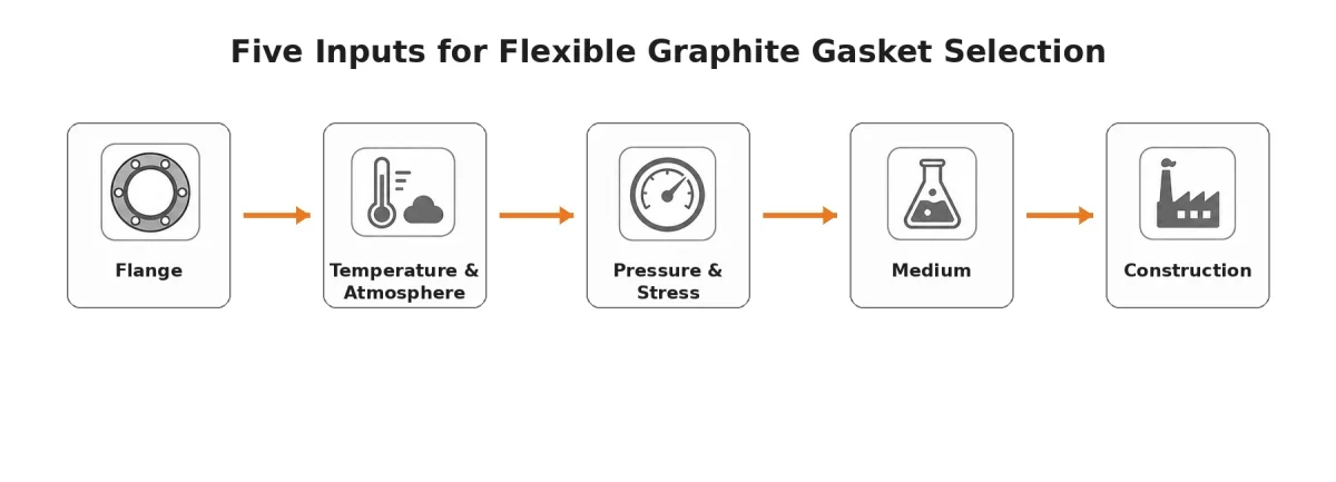
Start From the Flange, Not the Material

The flange face determines the gasket shape, available seating band and the way bolt load enters the material. A raised-face flange concentrates the load over a ring inside the bolt circle. A full-face gasket covers a larger area and includes bolt holes. Tongue-and-groove, male-and-female and confined joints restrain the gasket differently. Outside and inside diameter alone do not describe these load paths, so the quotation should identify the flange standard, class and facing or include a controlled drawing.
Face condition and alignment also matter. Flexible graphite can conform to small machining marks, but it cannot compensate for every groove, warped flange, misalignment or local loss of contact. The graphite sealing materials page shows available material forms, while the joint owner must define which flange defects are acceptable, repairable or cause for rejection under the applicable code, maintenance procedure and gasket design.
Radial width can still be calculated as a useful geometric input. For a simple ring with 300 mm outside diameter and 250 mm inside diameter, the nominal radial width is (300 − 250) ÷ 2 = 25 mm. If corrosion, a damaged land or a bore clearance removes usable contact, the effective loaded width becomes smaller. The example is arithmetic only; it does not establish a universal minimum width or a permitted defect depth.
A flange sketch should mark the bore, gasket OD, bolt-circle diameter, bolt count, hole diameter, contact band, facing, surface finish requirement and any local damage. For an existing joint, photographs after removal can help identify carbon transfer, radial washout, polished leak paths and uneven compression. The record should also note washers, bolt condition, lubricant, tightening method, repaired threads and any reason the available clamp load may differ from the standard assembly.
| Joint input | What the RFQ or drawing should record | Why it matters | Approval boundary |
|---|---|---|---|
| Flange identity | Standard, nominal size, class, facing, material and drawing revision. | Controls gasket dimensions, location and applicable standard. | Buyer or equipment engineer approves the flange basis. |
| Effective contact band | Bore, gasket OD, bolt holes, grooves, corrosion and actual seating width. | Controls loaded area and average gasket stress. | Use the approved drawing or measured joint condition. |
| Face condition | Finish, flatness/alignment method, local defects, reuse condition and repair history. | Changes contact distribution and leak risk. | No universal 0.3 mm, 0.5 mm or 1.0 mm rejection value is assumed. |
| Bolting and assembly | Bolt size/count/material, washers, lubricant, tightening method and target load. | Determines the clamp load transferred into the gasket. | Assembly procedure and load are approved by the joint owner. |
| Manufacturing geometry | Ring, full-face, pass partition, narrow bridges, holes and edge condition. | Changes cutting, handling and blowout risk. | DFM limits are confirmed for the selected sheet and cutting process. |
| Service history | Leak path, thermal cycling, corrosion, previous gasket and maintenance observations. | Helps separate material failure from joint or assembly failure. | Evidence informs selection but does not replace engineering approval. |
Temperature and Atmosphere Define the Material Envelope
Temperature must be stated with location, duration and atmosphere. The fluid temperature, exposed gasket-edge temperature, flange temperature and hot-side equipment temperature can be different. Continuous operation, startup, shutdown and short excursion conditions should be listed separately because graphite oxidation, metal-insert scaling and bolt relaxation respond to both temperature and time.
Atmosphere is decisive. A headline such as “graphite withstands 1000 °C” is incomplete. A named product may publish one limit in air, another in steam and a much higher value in inert or reducing media. For example, TEADIT GR2660/1660 publishes product-specific maximum-service values, while the GP 1520 and GR 1520 pages distinguish pure expanded graphite from metal-insert constructions. Those values belong to the named products and their stated conditions; they are not automatic limits for every grade supplied by our team, insert or gasket geometry.
The sealing materials and industrial gaskets solution can help identify the product family, but the purchase specification should name continuous temperature, excursion temperature, exposure time, internal atmosphere, external atmosphere, oxygen access at the gasket edge and the proposed insert material. Purity or oxidation-control requirements should be connected to an actual corrosion, oxidation or customer specification rather than selected only from a generic temperature band.
| Temperature and atmosphere input | Required project data | Material or construction question | Verification |
|---|---|---|---|
| Continuous service | Normal fluid, flange and exposed-edge temperature with expected operating hours. | Is the named graphite grade and reinforcement approved for that duration and atmosphere? | Named supplier data plus the project design basis. |
| Excursion or upset | Maximum temperature, duration, frequency and recovery condition. | Does the excursion change oxidation, insert, bolt or leakage risk? | Approved excursion review; do not copy a continuous limit. |
| Air or oxygen exposure | Oxygen access, edge temperature, ventilation and oxidation allowance. | Is an oxidation-controlled grade, edge protection or different construction required? | Grade-specific oxidation data or project testing. |
| Steam or process gas | Pressure, moisture, chemistry, cycling and contaminants. | Does the complete gasket construction remain suitable? | Named product data and joint qualification. |
| Inert gas or vacuum | Gas identity, oxygen level, vacuum range and external edge atmosphere. | Are graphite, insert and joint components all compatible? | Vacuum/leak plan with stated method and acceptance criteria. |
| Cryogenic duty | Minimum temperature, cycles, flange materials and assembly procedure. | Can the joint retain load and seal after contraction? | Application-specific qualification; no fixed three-cycle rule. |
Pressure Does Not Directly Set Gasket Stress
Internal pressure creates separating force, but bolt load seats the gasket. The same 2 MPa pressure can be manageable on a narrow, rigid joint with adequate bolting and difficult on a wide gasket with limited bolt area or poor assembly. Selection therefore needs the available clamp load, effective gasket area, assembly losses, operating separation force, flange rotation, thermal effects, required tightness and the permitted minimum and maximum gasket stress for the proposed construction.
A simple arithmetic example is useful when its limits are clear. If the bolts can deliver 320 kN total clamp load and the effective gasket area is 8000 mm², the initial average stress is 320,000 N ÷ 8000 mm² = 40 MPa. If the approved analysis assumes 30% total loss from scatter and relaxation, the remaining average would be about 28 MPa. These are teaching inputs, not recommended target stresses. A wider gasket increases area and may lower average stress unless available bolt load also increases.
Plain flexible graphite sheet has limited handling and tensile strength compared with reinforced constructions. Reinforcement may improve handling, cutting stability or resistance to extrusion and blowout, but it does not independently establish a pressure rating. Spiral-wound and metal-jacketed gaskets fall under different construction and dimensional rules. The graphite sealing article for valves, pumps and flanges further separates static flange gaskets from valve-stem and pump-shaft packing.
| Stress-control item | Input required | Calculation or evidence | Decision owner |
|---|---|---|---|
| Available assembly load | Bolt count, size, material, condition, lubricant, tool and tightening procedure. | Approved bolt-load or torque/tension method. | Equipment or joint engineer. |
| Effective gasket area | Loaded ID/OD, partitions, bolt holes and actual contact band. | Controlled drawing or measured joint geometry. | Gasket designer and buyer. |
| Minimum seating/operating stress | Named gasket construction and required tightness. | Supplier data, code method or qualified test basis. | Gasket designer. |
| Maximum permitted stress | Graphite density, reinforcement, flange strength and compression limit. | Named construction data and joint analysis. | Gasket designer and equipment engineer. |
| Losses and transients | Assembly scatter, relaxation, thermal expansion, pressure cycles and flange rotation. | Approved engineering assumptions and monitoring plan. | Joint owner. |
| Construction choice | Plain sheet, smooth-foil insert, tanged insert, spiral-wound or other design. | Selected from the complete joint analysis, not internal pressure alone. | Buyer and responsible engineer. |
Medium Compatibility Must Be Grade- and Construction-Specific
Flexible graphite is used with steam, oils, fuels, hydrocarbons and many acids and alkalis, but “graphite” alone is not a compatibility statement. Concentration, temperature, pressure, contaminants, oxidation potential, moisture, exposure duration, startup chemistry and the metal reinforcement can all change the result. Strong oxidizers remain a major warning group, and the insert or flange may be the limiting component even when the graphite itself is resistant.
The comparison with flexible graphite versus PTFE gaskets is useful only when the complete service is defined. A pH number is not enough. Hydrochloric acid concentration, oxidizing contamination and temperature must be known. Sodium hydroxide concentration, temperature and insert alloy must be known. Nitric acid or other oxidizing media require a specific compatibility review rather than an “often compatible” label.
Sulfur, chloride, ash and other trace limits may matter in corrosion-sensitive or cleanliness-sensitive service. The RFQ should state the limit, test method, reporting basis, lot definition and certificate requirement. A low ppm limit should not be inserted without a customer, corrosion or process reason, because purification cost can rise without improving the relevant sealing function.
| Medium review field | What must be provided | What must be checked | Outcome |
|---|---|---|---|
| Exact composition | Normal and upset composition, concentration, contaminants and phase. | Graphite grade, insert, flange and coating compatibility. | Approved, conditional, test required or unsuitable. |
| Temperature and pressure | Continuous/excursion temperature and operating/test pressure. | Compatibility at actual service, not room-temperature immersion alone. | Project-specific service envelope. |
| Oxidizing potential | Oxidizers, dissolved oxygen, chlorine species and electrochemical conditions. | Graphite oxidation and metal corrosion risk. | Specific review; no generic acid/alkali approval. |
| Exposure and cycling | Duration, startup/shutdown chemistry, cleaning and pressure/thermal cycles. | Ageing, loss of load, corrosion and leakage risk. | Qualification plan and inspection interval. |
| Purity limits | Carbon, ash, sulfur, chloride or trace-element requirements with method. | Whether the requirement is technically justified and measurable. | Purchase specification and certificate fields. |
| Uncertain service | Representative stressed specimen, full chemistry, time and temperature. | Mass, thickness, appearance, leakage or other approved responses. | Testing can screen risk but must match the intended claim. |
When Plain Sheet Is Appropriate
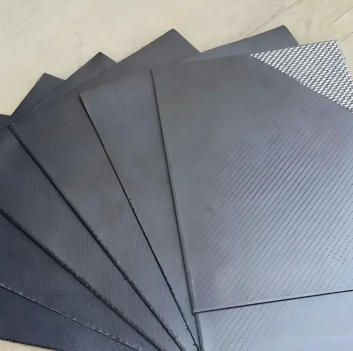
Plain flexible graphite sheet can be appropriate when the joint fully supports the gasket, handling damage is controlled, extrusion gaps are limited by the design, and the required dimensions can be produced without tearing or edge loss. Typical manufacturing routes include knife, punch, steel-rule die and CNC cutting. The cutting method, density, thickness, width and protective packing should be agreed before production.
Plain sheet is also used as filler, lamination stock and a supported sealing layer. When the requirement is an ultra-thin thermal or converter material rather than a flange gasket, the adjacent product may be better described as graphite paper or foil. The distinction matters because low-density sealing sheet, dense thermal sheet and synthetic pyrolytic graphite are not interchangeable.
The product form should be named as roll, sheet, panel or finished gasket. The flexible graphite sheet product page and graphite paper product page describe adjacent supply forms, but the RFQ must still state density, thickness, reinforcement, surface condition, dimensions and test requirements.
When Reinforcement or Another Gasket Construction Is Required
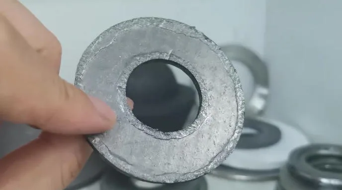
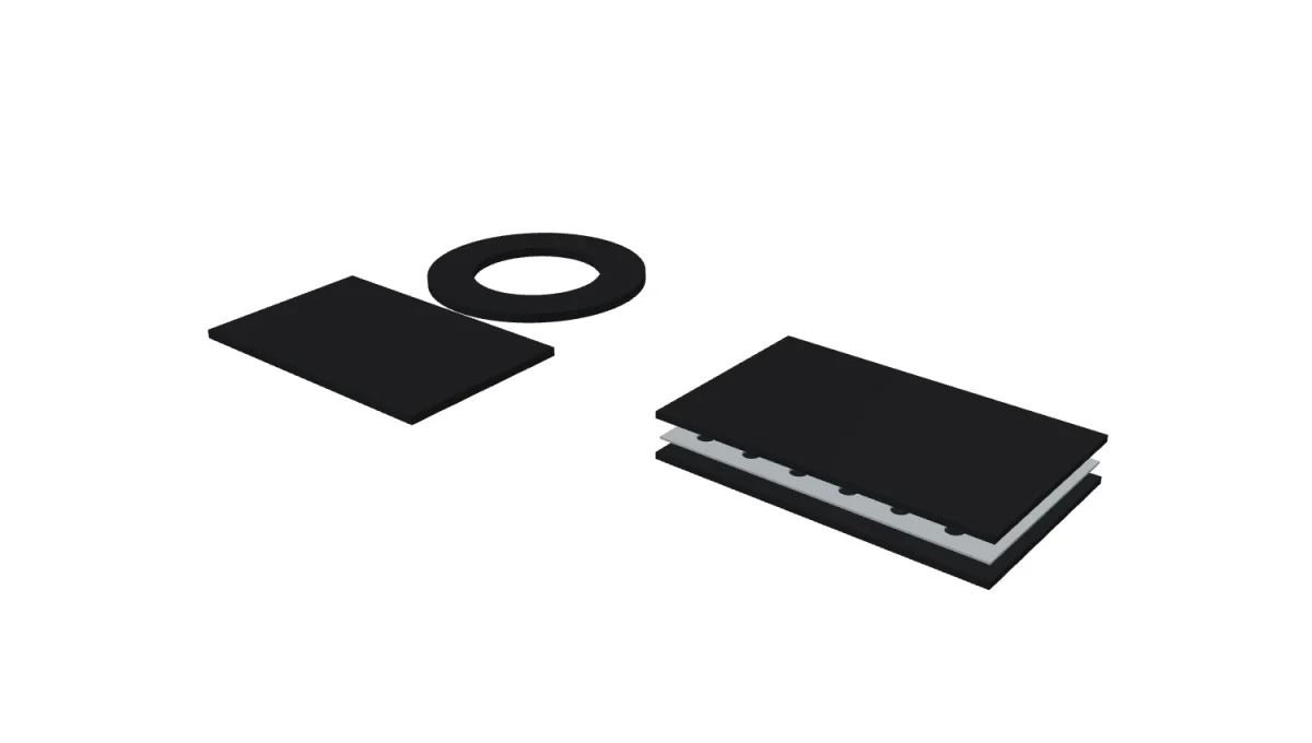
Reinforcement may be selected for handling strength, cutting stability, resistance to extrusion, mechanical support or blowout control. Smooth metal foil, tanged metal and other inserts behave differently during cutting and service. Insert alloy, thickness, graphite layer arrangement, mechanical engagement, edge exposure and corrosion compatibility should be specified.
A reinforced sheet is not automatically a higher-pressure gasket. The complete joint and construction still determine suitability. A spiral-wound gasket with graphite filler, a grooved metal gasket with facing layers or a metal-jacketed gasket has a different architecture and should be specified under the applicable standard and manufacturer data rather than described as a thicker version of sheet material.
Reinforcement also changes manufacturing. Smooth foil can leave a metal edge requiring controlled clearance or deburring. Tanged insert increases tool wear and can pull graphite from narrow lands when the punch is dull or the geometry is unsupported. Narrow bridges, closely spaced holes and exposed insert edges should be confirmed through DFM review and, where needed, a trial using the actual material and cutting tool. No single 6 mm or 8 mm bridge limit applies to every insert and die.
Replacement of Asbestos-Containing Gaskets Requires a Separate Work Plan
Replacing an asbestos-containing gasket with flexible graphite is not only a material-selection task. The old gasket must be handled under the applicable local law, site procedure and exposure-control plan. In the United States, OSHA states that classification of gasket removal as Class II or Class III work is site-specific and must be evaluated by the employer’s competent person. OSHA also explains that glove-bag requirements depend on the work classification, material condition and removal circumstances; the OSHA interpretation on asbestos-containing gasket removal should therefore be read in its U.S. construction or shipyard regulatory context.
The material-conversion issues are discussed separately in the flexible graphite roll asbestos-substitution article. The replacement package should record the legacy gasket, service condition, flange and bolting, leak history, removal controls, proposed graphite construction and qualification basis. A new gasket material does not correct damaged flanges, missing bolts or an uncontrolled tightening procedure.
Thickness, Tolerance and Quality Evidence for Gasket Cutting
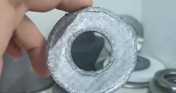
Thickness affects handling, cutting, seating, compression and flange movement. Our team can quote common thin, general and thicker flexible-graphite constructions, but the nominal thickness must be paired with density, reinforcement and tolerance. A 1.0 mm plain sheet and a 1.0 mm reinforced sheet do not have the same internal stack or cutting behaviour.
A percentage tolerance should be converted to an actual dimensional range before approval. For example, ±10% equals ±0.10 mm at 1.0 mm and ±0.30 mm at 3.0 mm. The drawing or purchase order should distinguish average thickness, local thickness, measurement locations, conditioning, instrument, contact pressure and sampling. A broad flange gasket and a shim-like stack may require different controls.
ASTM F36 covers short-time compressibility and recovery of gasket materials under its stated test conditions and explicitly does not replace prolonged-stress creep testing. ASTM F38 addresses creep relaxation, while ASTM F104 is a classification system whose own scope warns that not all properties contributing to performance are included. These methods can support a data package, but the buyer must specify the edition, specimen, conditioning, method and acceptance value.
Width and length affect conversion yield. A 1000 mm roll divided into four 240 mm lanes leaves 40 mm for edge trim and knife loss; a 960 mm roll leaves no process margin. This arithmetic is valid as a layout example, but actual nesting, trim, splice allowance, core ID, maximum roll weight and sheet orientation must come from the converter’s plan.
Packaging should protect flatness, clean surfaces and vulnerable edges. The graphite packaging and logistics article and graphite export documentation guide cover physical and documentary controls. The order should state whether supply is in rolls, sheets, reinforced panels or finished gaskets; whether splices are allowed; and how lots, labels, certificates and package quantities are identified.
What the Quotation Needs From You
A usable RFQ should include the flange standard or drawing, facing, gasket dimensions, continuous and excursion temperature, internal and external atmosphere, operating and test pressure, exact medium composition, bolt information, assembly method, required construction, nominal thickness, density, reinforcement, carbon or impurity limits, inspection requirements, quantity and destination. Unknown items should be marked unknown rather than silently replaced with generic assumptions.
The RFQ should also state the required manufacturing route. Roll stock for continuous die-cutting needs width, usable length, core ID, winding and maximum roll weight. Sheet or panel stock needs dimensions, flatness or handling criteria and pallet limits. Reinforced sheet needs insert type, alloy, thickness and an answer on whether exposed metal at cut edges is acceptable.
A concise project example can demonstrate the fields without creating a default specification: “Raised-face steam flange; 300 °C continuous and 350 °C excursion; 2.5 MPa operating and 4.0 MPa hydrotest; 220 mm OD and 150 mm ID; eight M20 bolts; specified facing; buyer-proposed 1.5 mm reinforced construction; 500 trial pieces and 10,000 annual pieces.” Every value in this example is a buyer input. It does not establish a universal temperature, pressure, thickness or bolt recommendation from us.
Our team supplies plain and reinforced flexible graphite sheet, roll and panel forms for industrial gasket manufacturing against agreed specifications. The graphite sealing materials, graphite products range and graphite paper properties article help distinguish adjacent material forms. Project communication guidance can be used to keep drawing revisions and operating conditions aligned.
Send the available flange and service information through the contact page. QDZRT Graphite can review the material and conversion inputs, identify missing RFQ fields and quote the agreed supply form. Final gasket design, code compliance, assembly procedure and service qualification remain with the responsible buyer, gasket designer and equipment engineer.