Thermal management covers two different jobs. In an electronic assembly, heat must spread away from a small source through a thin stack. In a furnace, the material may sit beside a 900 °C chamber and remain dimensionally useful through repeated cycles. Both jobs involve heat, but they do not call for the same graphite form.
QDZRT Graphite supplies flexible graphite sheet, graphite block, custom graphite machined parts and expandable graphite. The selection starts with operating temperature, atmosphere, heat path, mechanical load and service time. A material that survives a short laboratory exposure is not automatically suitable for continuous plant operation.
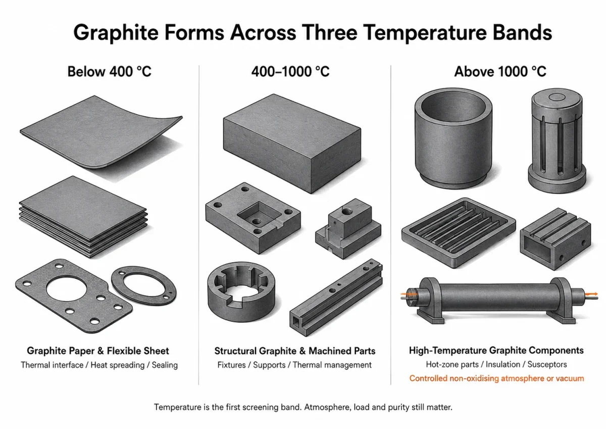
Temperature Sets the First Screening Band
Temperature changes conductivity, oxidation rate, binder stability, adhesive performance, mechanical strength and allowable atmosphere. It also changes the meaning of “graphite.” A 0.05 mm heat-spreading film, a 1.0 mm flexible sheet and a 100 mm synthetic graphite block are all carbon-based products, yet their structure and duty are different.
The maximum service temperature cannot be quoted without the surrounding gas. Graphite remains structurally useful at very high temperature in vacuum, argon or another controlled non-oxidising environment. In air, oxidation removes carbon and weakens the body. Oxygen leakage, steam and carbon dioxide can therefore set the service ceiling long before the graphite lattice reaches a thermal limit, so atmosphere composition and permitted oxidants must be treated as part of the material specification.
Pressure changes the picture again. A vacuum furnace may reduce convective heat transfer while increasing the importance of radiation and solid contact. A pressurised inert-gas furnace can move heat by convection and expose every joint to gas flow. The same graphite plate can therefore run at a different surface temperature in two systems with the same chamber setpoint. Thermocouple position, emissivity and contact area affect the measured result.
Duration matters as much as the peak. A component exposed to 650 °C for 30 seconds during a process upset faces a different mass-loss risk from one held at 650 °C for 8000 hours. Temperature cycling adds expansion mismatch at joints and can loosen contact pressure. For a thin thermal pad, the first limit may instead be an acrylic adhesive rated near 120 °C or a polymer liner removed before assembly.
The following temperature bands are an illustrative screening framework for an RFQ discussion, not catalogue ratings or product-life guarantees. Final selection must use the actual grade, geometry, atmosphere, pressure, load, exposure time, cycle profile and adjoining materials.
| Temperature band | Typical duty | Candidate graphite form | Dimensions to confirm | Atmosphere review | First adjacent-material or process limit | Service data required |
|---|---|---|---|---|---|---|
| 20–120 °C | Continuous electronics and compact assemblies | Graphite paper or laminated heat-spreading pad | Finished thickness, area, die-cut geometry and complete stack | Ambient or enclosed air; check electrical insulation and condensation | Adhesive, liner, carrier film or insulating layer | Normal and peak temperature, continuous hours, contact pressure and cycle count |
| 120–250 °C | Power devices and heated process surfaces | Plain graphite paper, flexible graphite sheet or qualified laminate | Thickness, density, flatness and interface geometry | Air or enclosed process gas; confirm oxygen exposure and ventilation | Binder, carrier film, adhesive and neighbouring metal or polymer | Peak dwell, continuous exposure, cycle profile and clamping condition |
| 250–400 °C | Short process cycles, sealing interfaces and uncoated thermal layers | Uncoated flexible graphite or application-specific graphite part | Compressed thickness, edge restraint and finished dimensions | Air exposure requires a grade- and cycle-specific oxidation assessment | Oxidation, fixture compatibility and loss of polymeric stack materials | Oxygen level, time at temperature, number of cycles and acceptance method |
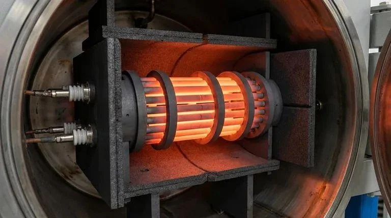
| 400–1000 °C | Furnace and process equipment | Graphite block, plate or machined component | Section size, orientation, machining allowance and load path | Assess any air exposure separately; otherwise define controlled process gas or vacuum | Oxidation rate, joints, fasteners, insulation and product-contact contamination | Atmosphere composition, flow, pressure, ramp, dwell, load and replacement basis |
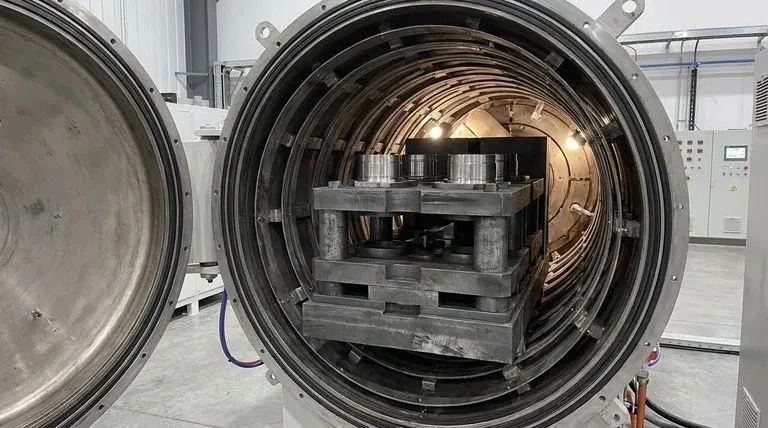
| 1000–2000 °C | Vacuum or controlled-atmosphere hot zone | Selected graphite block and finished hot-zone parts | Geometry, section thickness, joint design, orientation and tolerance at reference temperature | Controlled non-oxidising atmosphere or vacuum; review reactive process gases and leaks | Impurity transport, thermal gradients, joint contact and insulation design | Vacuum level or gas specification, residual oxidants, cycle profile and contamination limits |
| 2000–3000 °C | Specialised thermal processing in purpose-designed equipment | Application-qualified graphite hot-zone components | Application-specific geometry, support, joint and inspection requirements | Purpose-designed vacuum or compatible purified-gas system | Sublimation, vapour transport, contamination and equipment capability | Full process-gas, pressure, temperature, duration, cooling and inspection plan |
These bands organise the first screening questions only. They do not establish a maximum service temperature, stock capability or expected life. The approved grade specification and the confirmed operating conditions control the actual limit.
Below 400 °C: Where Most Electronics Live
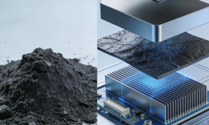
Below 400 °C, thermal management is dominated by interfaces and heat spreading, but a thin layer still requires control of orientation, handling, electrical insulation and contact conditions. A processor, power module or battery component can create a local hot spot over a few square millimetres. The graphite layer spreads energy laterally into a larger metal frame, heat sink or chassis area. High in-plane conductivity matters more than bulk structural strength.
Thin graphite paper supports heat spreading when the assembly can protect its edges and electrically conductive surface. Flexible graphite sheet is thicker and more compressible, which helps conform to uneven surfaces but changes the thermal path through thickness. The article on flexible graphite foil versus thermal graphite sheet separates these two product concepts.
A 0.05 mm film can fit a phone or compact control module, but it tears more easily during die cutting and assembly. A 0.5 mm flexible sheet tolerates compression and rougher handling, yet occupies ten times the thickness. Density changes flexibility, surface strength and contact. The selection therefore uses the complete stack: source surface, graphite, adhesive or liner, insulating film and receiving metal.
Adhesive is frequently the lowest-temperature component. A graphite layer may remain stable while the adhesive softens, pumps out or loses peel strength. Electrical insulation can also become the deciding requirement because graphite conducts electricity. The graphite-paper pad conversion article covers slitting, lamination and die cutting, while graphite paper in electronic thermal management focuses on the assembled heat path.
At 250–400 °C, polymer layers disappear from many designs. Plain flexible graphite can remain, but air exposure and metal compatibility need evaluation. A short sealing or process cycle is not equivalent to continuous electronic operation. State peak temperature, time above 250 °C and the number of expected cycles.
Contact pressure also changes thermal resistance. A soft graphite layer can conform to machining marks and increase real contact area, but excessive compression thins the layer and may cause lateral movement at an unrestrained edge. The assembly drawing should identify the clamping method and the available compression. A free-standing film tested between polished laboratory plates does not predict performance between a cast housing and a stamped cover.
400–1000 °C: Furnace and Process Equipment
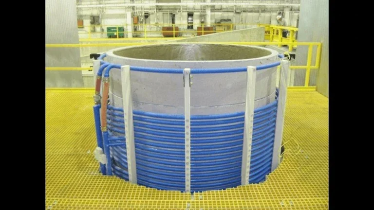
Between 400 °C and 1000 °C, the material form often moves from film toward structural graphite because plates, rails, susceptors, supports, heating-zone fixtures and machined channels may carry their own weight, contact loads or thermal gradients. Density, grain size, strength and purity now sit beside conductivity.
Atmosphere divides the band. In air, graphite oxidation becomes a design issue and can accelerate with temperature, flow velocity and catalytic impurities. In nitrogen, argon or vacuum, much higher service temperatures are possible, but leakage and process gases remain relevant. Steam and carbon dioxide can react with graphite at elevated temperature even when free oxygen is low.
A furnace plate 500 × 300 × 20 mm needs enough section to resist handling damage and thermal stress. A thin graphite-paper layer cannot replace it. A machined distributor with 2 mm holes needs a fine-grain block and a toolpath designed for brittle carbon. The graphite block industrial-use guide explains the block forms, and graphite machining challenges covers dust, thin features and dimensional control.
Heat flow through a furnace part can be intentional or undesirable. A graphite susceptor couples energy and transfers heat to the load. An insulation support needs mechanical stability with limited heat leakage. Grade selection follows that function. A high conductivity value is not automatically an advantage when the purpose is to reduce heat loss.
Repeated cycling can expose differences in thermal expansion between graphite, ceramic, metal fasteners and insulation. Slots, sliding joints or clearances may be necessary. The drawing must state the reference temperature for dimensions. A 0.10 mm room-temperature clearance can close when neighbouring materials expand at different rates.
Furnace contamination deserves a separate line in the RFQ. Ash that is harmless in a general heat-treatment fixture can deposit on a semiconductor wafer, react with molten metal or stain a ceramic surface. State whether the component touches the product, sits in the hot zone or remains behind insulation, because the location and contamination mechanism determine whether a carbon-content, ash or trace-element specification is required.
Above 1000 °C: Controlled Non-Oxidising Atmosphere or Vacuum
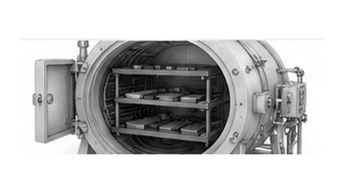
Above 1000 °C, an oxidising atmosphere is not a normal continuous-service environment for graphite. High-temperature use therefore requires vacuum or a controlled non-oxidising atmosphere compatible with the process, together with defined limits for leaks, residual oxygen, water vapour, carbon dioxide and other reactive process gases.
Graphite block and machined components serve hot zones, heaters, crucibles, supports and thermal-field structures. Purity becomes a process variable because residue and specific trace elements can volatilise or contaminate the workpiece. Carbon content, ash and individual elemental limits are separate specifications: the carbon figure must state its calculation basis and analytical method, while ash and critical trace elements should be specified independently when the process requires them. The official ASTM C561 test-method page describes ash as the non-combustible residue obtained by the method and notes that the result does not determine the composition of the mineral matter.
Strength does not simply fall with temperature in the same way as many metals, but oxidation damage, pores and thermal gradients still govern failure. A thick block can survive a high uniform temperature and crack during rapid cooling because the surface and centre move through different temperatures. Ramp rate, section thickness and fixture restraint belong in the operating description.
At 2000–3000 °C, graphite is used only in specialised systems designed for those conditions. Vapour transport, sublimation, joint contact and insulation design become significant. No catalogue temperature can replace an atmosphere and equipment review.
Fast heating can create a radial or through-thickness gradient before the centre approaches the surface temperature. The response depends on section size, geometry, grade, heat input, surface condition, restraint and cooling path rather than on thickness alone. If one face receives radiant heat while the opposite face is cooled through a fixture, internal thermal stress may exceed the stress from external loading. A thermal model or staged trial is valuable for thick sections, rapid transients, asymmetric heating or geometries with sharp internal corners; the allowable ramp should be established for the actual part and equipment.
Oxidation: The Real Ceiling
Graphite’s high-temperature reputation can hide its oxygen sensitivity.
Oxidation removes solid carbon as gaseous products. Early mass loss opens pores and reduces the load-bearing section before a dramatic visual failure appears. Temperature, oxygen partial pressure, gas flow, graphite microstructure and impurities all affect the rate. The U.S. Department of Energy report Oxidation Behavior and Property Degradation of Nuclear Graphites documents the relationship between oxidation, microstructure and property loss.
Mass loss is more useful than appearance alone. A part can retain its outline after losing material from internal pore surfaces. Weighing a clean reference coupon before and after a defined exposure gives a direct result, while dimensional checks reveal local recession. For a load-bearing component, neither result is enough by itself; retained strength or a conservative replacement interval may be required.
The following is an illustrative RFQ and service-test planning template. It does not supply acceptance limits. Each project must define the method, measurement location, initial baseline, instrument capability, sample plan and approved criterion before testing begins.
| System condition | Temperature and cycle field | Atmosphere field | Measurement method to agree | Sampling field | Acceptance criterion to define |
|---|---|---|---|---|---|
| Electronic pad | Normal temperature, peak temperature, dwell and ageing duration | Ambient or enclosed-air condition, humidity and contamination exposure | Thermal resistance, thickness, visual condition and adhesion method where applicable | Lot size, sample quantity, locations and preconditioning | Approved limits for thermal change, dimensions, adhesion and visible damage |
| Process sheet or flexible graphite layer | Peak temperature, dwell, heating/cooling rate and cycle count | Oxygen level, gas flow, pressure and other reactive species | Pre/post mass, thickness, surface condition and functional test | Coupon orientation, quantity, edge condition and measurement locations | Agreed mass, dimensional and functional limits for the stated method |
| Furnace support or structural part | Operating temperature range, load, dwell and replacement cycle | Gas composition, flow, residual oxidants, pressure or vacuum level | Mass, dimensions, crack inspection and retained property where required | Part or coupon plan, inspection positions and frequency | Drawing- and grade-specific limits linked to the approved inspection method |
| Vacuum hot-zone component | Temperature profile, ramp, dwell, cooling method and total cycles | Base pressure, operating pressure, leak condition and process-gas composition | Dimensions, joint contact, surface recession, contamination and crack inspection | Every-part or lot plan according to criticality and drawing requirements | Approved dimensional, visual, contamination and functional criteria |
| Purification or ultra-high-temperature fixture | Full temperature and time profile, including heating and cooling transients | Vacuum or purified-gas specification and permitted residual species | Ash or elemental analysis by agreed method, mass change and dimensional inspection | Lot definition, sample selection and traceability to the processed batch | Application-specific ash, elemental, dimensional and structural limits |
A service test must reproduce the actual atmosphere, load and cycle, and the report must identify the grade, specimen orientation and measurement method. The IAEA graphite knowledge base explains that graphite thermal conductivity is anisotropic and that reported high-temperature conductivity depends on temperature and measurement direction. A conductivity value should therefore be used only with its stated grade, direction, temperature and method.
Matching Product Form to the Temperature Band
Below 120 °C, laminated graphite paper can combine heat spreading with assembly convenience. From 120–250 °C, plain graphite paper or a qualified high-temperature laminate may be necessary. From 250–400 °C, uncoated flexible graphite avoids polymer degradation but still requires an oxidation and fixture-compatibility review. Temperature is the first screening band, while the stack, atmosphere and duty determine the final form.
From 400–1000 °C, select block, plate or a machined component according to load, geometry, atmosphere and contamination limits. Above 1000 °C, the selected grade, purification level and finished-part requirements should be determined by product contact, contamination sensitivity and the controlled non-oxidising atmosphere or vacuum system; purified material is not automatically necessary for every non-contact component. Expandable graphite occupies a different role: it is an intercalated raw material whose expansion under heat supports fire-protection and functional formulations, not a structural hot-zone block. Our protective coatings and fire-protection page covers that route.
The product form must also fit fabrication. Rolls suit continuous slitting and die cutting. Sheets suit small batches. Blocks suit machining. Finished parts suit assemblies where the drawing, material and inspection need one controlled supply. The thermal-management and high-temperature solution page connects these forms to their application families.
A product transition can occur inside one machine. Flexible graphite may seal a service flange at 350 °C, a molded block may support a 700 °C fixture and an isostatic graphite component may sit inside a 1500 °C vacuum zone. Treating all three as one “thermal graphite” purchase hides the fact that their density, purity, thickness and inspection methods are different.
What to Confirm Before Ordering
State minimum, normal and maximum temperature. Add continuous exposure time, cycle count, heating and cooling rates, atmosphere composition, pressure or vacuum level and permitted oxygen. Define whether the graphite spreads heat, conducts heat through a structure, supports a load, seals an interface or expands during a fire event.
For thin material, specify thickness, density, roll or sheet dimensions, adhesive, liner, electrical insulation and finished die-cut geometry. For block and parts, specify forming route, density, grain size, purity, dimensions, tolerances, orientation and inspection. The order also needs packaging that protects film edges, sheet flatness or machined corners.
A complete thermal description prevents a low-temperature pad specification from being applied to a furnace part. Start the inquiry through the contact page with the temperature profile, atmosphere, heat path and available space. After we reply, send the controlled drawing by email or another agreed secure channel. Our team can then discuss the product form that fits the actual temperature band.