Custom graphite parts appear in semiconductor equipment, high-temperature furnaces and EDM tooling because graphite combines heat resistance, machinability, dimensional stability and application-specific geometry. Those shared properties do not make the three industries interchangeable.
QDZRT Graphite supplies custom graphite machined parts from selected graphite block. Semiconductor hardware can be driven by trace contamination and cleaning. Furnace components are governed by temperature, atmosphere and thermal stress. EDM electrodes are judged by electrical discharge performance, wear and the surface left in the workpiece.
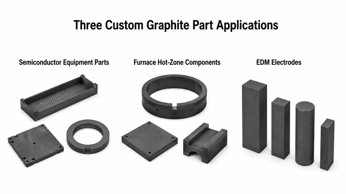
The Same Material, Three Very Different Jobs
The phrase “machined graphite part” describes a manufacturing route, not a complete specification. A 200 mm furnace support, a 50 mm semiconductor fixture and a 100 mm EDM electrode can all begin as fine-grain synthetic graphite. Their release documents, cleaning methods and critical dimensions are still different.
The first review therefore separates function from geometry, because application comes before grade. A ring may locate a wafer, shield radiation or carry current. A plate may support insulation, distribute gas or become an EDM tool. The same outside dimensions can hide different failure consequences. Once the function is clear, the drawing can identify which surfaces, holes and edges are critical and which areas can carry open tolerances.
Semiconductor-related equipment places material near wafers, process gases, heaters or deposition zones. Uncontrolled ash, metals or handling residue can affect the process. A drawing may include gas channels, vacuum features and thin walls whose cleanliness is as important as size.
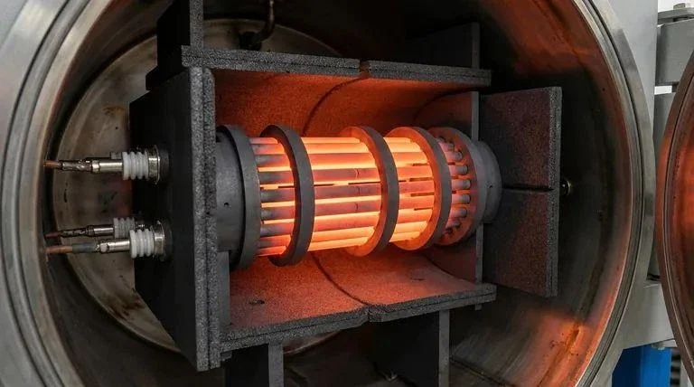
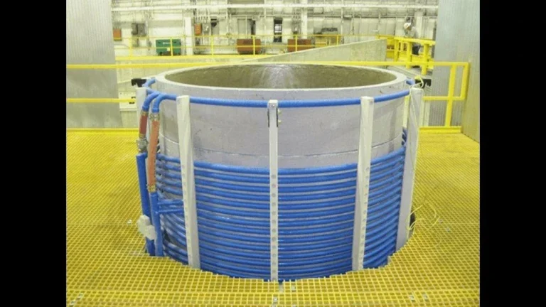
A furnace part works through thermal cycles. It may support a load, conduct current, couple induction energy, shield heat or position another component. Grade selection, coefficient of thermal expansion and oxidation behaviour can dominate.
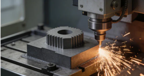
An EDM electrode is a consumable tool. It must reproduce geometry through controlled electrical discharges while resisting corner wear and maintaining flushing paths. Grain size, resistivity and electrode design connect directly to machining time and cavity finish.
| Application | Required project inputs | Illustrative RFQ screening examples | Acceptance basis |
|---|---|---|---|
| Semiconductor fixture | Approved grade, density or grade reference, particle-size method, carbon-content basis, ash method, element-specific limits, drawing tolerances and cleanliness definition | A project may screen density around 1.75–1.90 g/cm³, particle size around 5–20 µm and tolerances around ±0.02–0.10 mm. These are non-universal enquiry examples, not a product specification. | Approved material data, controlled drawing, agreed chemistry methods, dimensional report and cleanliness plan |
| Furnace support | Operating temperature, atmosphere, load, blank orientation, section size, thermal clearance, grade and inspection scope | An early enquiry may mention density around 1.65–1.90 g/cm³, particle size around 10–800 µm and tolerances around ±0.10–0.50 mm, subject to the selected grade and hot assembly. | Approved grade data, orientation record, drawing dimensions and project-specific visual or property checks |
| EDM roughing electrode | EDM machine and workpiece material, roughing strategy, wear target, surface requirement, electrode geometry, resistivity and strength requirements | Screening may include density around 1.70–1.85 g/cm³, particle size around 10–50 µm and tolerances around ±0.03–0.10 mm, but the actual grade and offset come from the EDM process plan. | Controlled electrode drawing, approved grade properties, dimensional inspection and agreed trial or process validation |
| EDM finishing electrode | Required cavity finish, detail retention, wear limit, spark allowance, flushing features, grade and inspection method | An enquiry may use density around 1.78–1.90 g/cm³, particle size around 1–15 µm and tolerances around ±0.01–0.05 mm as examples only. | Approved electrode design, grade-specific data, critical-feature report and required surface verification |
The table is an illustrative RFQ screening framework, not a declaration of a universal material range from us or a substitute for a controlled specification. A specific grade may fall outside an example while remaining correct for the application. The approved material record, drawing, test methods and agreed inspection plan control the order.
Semiconductor Equipment Parts
Semiconductor-related graphite parts include susceptors, rings, plates, carriers, heaters, shields and fixtures. The component may sit in vacuum, inert gas or a reactive process atmosphere. It can touch the product, face the process space or remain behind another layer. That location sets the purity and cleaning requirement.
Carbon content, ash and element-specific impurity limits are separate acceptance items. A reported carbon percentage may use a calculation by difference or another agreed basis, but it alone does not define ash or the concentration of iron, sodium, calcium or other process-sensitive elements. ASTM C561 describes ash as a practical estimate of nonburnable residue and does not establish the mineral content of the sample. When the application requires element-specific limits, the order should name the elements, reporting units and method; ASTM D8186 is one method covering multiple trace impurities in graphite. Purification and final cleaning should then be controlled so that accepted chemistry is not compromised during handling.
Geometry can be delicate. Gas holes below 2 mm, slots near 1 mm, walls of 1–3 mm and a ring containing 48 small holes are useful examples of features that can increase machining and inspection risk, but they are not universal manufacturability limits. The result also depends on grade strength, feature depth, aspect ratio, edge distance, tool entry, fixturing, cleaning access and the inspection method. A small radius or relief can improve yield where the functional envelope permits it.
Inspection combines dimensions and cleanliness. A coordinate report can verify datums and hole positions. Visual inspection checks chips, cracks and blocked passages. Clean packing separates the finished part from foam, wood dust and ordinary workshop debris. The semiconductor graphite-parts guide expands on drawing, material and packaging requirements.
Batch identity must survive purification and machining. If several billets enter one production lot, the certificate needs to identify whether chemistry represents each billet or a combined batch. Replacing a grade after the first approval can alter thermal expansion, strength or impurity profile even when the outside dimensions remain unchanged.
Cleaning acceptance also needs a measurable basis. “Clean for semiconductor use” can refer to visible dust, non-volatile residue, particle count or selected elemental contamination. Those are different tests. A practical order states the surfaces to be cleaned, the permitted packaging materials and whether the part may be touched by bare hands or only with approved gloves after final inspection. Cleanliness is therefore a product characteristic with its own acceptance method, not a general label. Without those details, a supplier can meet the drawing and still miss the process expectation.
Furnace and Hot-Zone Components
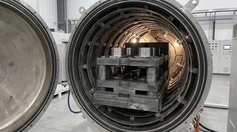
Furnace graphite includes rails, plates, supports, posts, heaters, connectors, crucibles, shields and thermal-field structures. The first question is atmosphere. In air, oxidation consumes graphite. In vacuum or inert gas, much higher temperatures may be possible, but process gases and oxygen or moisture leakage still matter because atmosphere control is part of the service-life assessment.
The U.S. Department of Energy report Oxidation Behavior and Property Degradation of Nuclear Graphites provides background on how oxidation, graphite microstructure and property loss can be connected in nuclear-graphite studies. It does not define an industrial-furnace grade, temperature rating or service life. Furnace selection must still use the actual grade data together with operating temperature, exposure time, gas composition, oxygen or moisture leakage and the consequence of section loss.
A large support does not always need 10 µm grain. Coarser molded or extruded stock can offer an economical section when tolerances are open and thin features are absent. A heater with narrow current paths or a fixture with many small holes benefits from a finer, more uniform grade. The graphite block application guide and high-temperature processing solution show the wider material context.
Orientation matters in molded and extruded stock. A long member can be cut along the extrusion direction, while a wide plate may cross it. Thermal expansion and strength differ by direction. The drawing should identify the principal load and heat-flow directions so the blank can be nested correctly.
Furnace tolerances need an operating reason. A support with a project clearance of ±0.5 mm may be adequate for one hot assembly, while another interface may require ±0.02 mm. The tighter value is not by itself better because fit, load path, reference temperature, inspection capability and thermal expansion all matter. Final tolerances must be derived from the actual assembly and stated at a defined reference temperature rather than copied from a room-temperature machining convention.
Thermal shock depends on section change, grade, restraint and the approved operating cycle. A 40 mm plate connected to a 4 mm web is an illustrative geometry that may develop a temperature gradient because the thin region can respond faster than the thick region. A generous internal radius can reduce local stress concentration where the sections meet. If the geometry cannot change, a slower ramp may be considered only after the equipment owner confirms the material, heat flux, support conditions and cycle; the dimensions alone do not establish one universal ramp rate.
EDM Electrodes
EDM graphite is selected for discharge behaviour, wear, machinability and the required cavity finish. Grain size is one selection variable rather than a rigid roughing-versus-finishing rule. Supplier examples show that an ultrafine grade such as EDM-1 can be used for high-detail roughing, while a superfine grade such as EDM-200 is listed for both roughing and finishing electrodes. Grade selection should consider strength, wear, resistivity, discharge settings, feature size and required finish together. Density alone does not predict the result.
Grain size affects corner retention and the minimum feature that can be machined reliably. Electrical resistivity influences discharge conditions. Flexural strength helps thin electrodes survive handling and flushing pressure. The EDM graphite electrode basics and EDM block selection guide connect these properties to electrode use.
Electrode dimensions are not always identical to cavity dimensions. Spark gap, orbiting strategy and wear compensation alter the required geometry. Those values belong to the EDM process design. Our team machines to the supplied electrode drawing; it does not infer a cavity offset from the workpiece model unless that engineering scope is explicitly agreed.
Flushing holes, thin ribs and deep pockets change machining risk. A Ø1.0 mm hole through 60 mm of graphite needs a different approach from a Ø6 mm hole through 20 mm. The article on thin walls and small holes explains why these features change quoting and yield.
Electrodes also need identification. Part number, cavity position, roughing or finishing status and orientation can be marked on a non-working face. Packing must protect corners because a 0.2 mm chip can transfer into the cavity.
Machining allowance must be separated from spark allowance. The first belongs to manufacture of the graphite electrode; the second belongs to the EDM process. If a cavity requires a 0.15 mm spark gap per side, the electrode drawing should already contain that offset or state clearly that it does not. Roughing and finishing may use different electrodes, settings or wear strategies, but the selected grade is not determined by particle size alone. Mixing the two allowance assumptions produces an electrode that is dimensionally correct to the wrong model.
Why One Grade Cannot Cover All Three
The optimum grade changes with the failure mode. Semiconductor parts can fail through contamination, blocked passages or dimensional drift. Furnace parts can fail through oxidation, thermal shock, creep of the surrounding assembly or wrong grain direction. EDM electrodes can fail through edge wear, chipping, unstable discharge or excessive machining time.
| Application | Primary control variables | Required project inputs | Acceptance method | Packaging and handling |
|---|---|---|---|---|
| Semiconductor equipment part | Trace elements, ash, surface residue, small passages, critical datums and process-facing surfaces | Material grade, chemistry limits and methods, controlled drawing, cleaning definition and restricted packaging materials | Dimensional report, visual inspection, agreed cleanliness test and lot traceability | Approved clean bags or wrapping, handling restriction, part and lot identification |
| Furnace hot-zone component | Atmosphere, temperature cycle, section transition, load, grain direction and thermal clearance | Operating window, assembly drawing, reference temperature, grade, orientation and replacement criteria | Envelope dimensions, orientation record, visual integrity and any agreed property or fit checks | Corner and surface protection, moisture control where required, orientation and batch labels |
| EDM electrode | Wear, resistivity, strength, flushing, spark geometry, surface target and feature retention | Roughing or finishing strategy, electrode drawing, included offset, machine conditions, workpiece and cavity identification | Critical dimensions, grade record, visual inspection and agreed EDM trial or process evidence | Individual corner protection and clear cavity, revision, orientation and status labels |
One expensive ultrafine grade is not by itself safe for every part. It can be unavailable in the required furnace size, unnecessary for an open-tolerance support or chemically inadequate for a semiconductor process unless it receives the required purification.
Cost also appears in yield. A semiconductor ring containing 48 small holes is an illustrative case in which one breakout may reject a completed part, depending on the hole depth, edge distance, grade and acceptance rule. A furnace block with open tolerances may be cut from larger stock with high yield. An EDM electrode family can share one billet if grain direction and traceability remain acceptable. Price per kilogram therefore gives little information about cost per accepted part. Stock availability, machining time, inspection and rejection risk need to be compared together.
Drawing Information Each Industry Needs
Every drawing needs revision, units, datums, material callout, dimensions, tolerances, edge treatment and quantity. Industry-specific information then sits on top.
A semiconductor drawing needs process-facing surfaces, no-touch areas, cleanliness level, restricted materials, vacuum or gas passages and packaging. A furnace drawing needs operating temperature, atmosphere, load direction, grain orientation, reference temperature and thermal clearance. An EDM drawing needs roughing or finishing status, electrode offset already included or not, flushing features, cavity identification and non-working marking area.
Inspection features must be accessible. A callout for a deep internal diameter needs an instrument and approach that can reach it. A surface-finish requirement inside a 1.5 mm slot may not be measurable by the same method used on an open face. The drawing can identify witness coupons or a process-based acceptance when direct measurement is impossible. That decision belongs before quotation, not after parts are complete.
The graphite drawing-review article, tolerance confirmation guide and precision machining guide explain how a metal drawing needs adjustment for brittle graphite.
Machining generates graphite dust. The NIOSH Pocket Guide for synthetic graphite provides occupational-exposure information, measurement-method references and health-hazard background. It supports hazard identification and control assessment, but it does not prescribe one universal dust-extraction or cleaning system. The actual controls should follow the workplace risk assessment, applicable requirements and the need to keep finished passages open.
Lead Time and Batch Control
Lead time begins with stock availability. A standard EDM billet can be available while a 600 mm isostatic furnace block requires production. Purification, test chemistry, prototype machining and dimensional reporting add separate time. A requested delivery date needs to distinguish raw-material approval, first article and remaining quantity.
Prototype quantity affects the route. One semiconductor fixture may be machined from available stock and inspected completely. A 100-piece repeat order can justify dedicated stock, fixtures and a sampling plan. A furnace replacement may need immediate machining from a larger billet to reduce downtime. An EDM program may release roughing electrodes first and finishing electrodes after cavity strategy is confirmed. One delivery date cannot describe these different release points.
Batch control keeps grade, billet and certificate connected to the finished part. Semiconductor work may require segregation through cleaning and packing. Furnace work needs orientation marking and replacement consistency. EDM orders need electrode identity by cavity and revision.
A replacement part should not rely only on the old item’s outside measurements. Used furnace graphite can oxidise and shrink at the surface. An EDM electrode can be intentionally undersized for spark gap. A semiconductor part can contain hidden passages or cleanliness notes not visible in a sample. The controlled drawing and approved material record remain the safest basis for repetition.
A repeat drawing is not by itself a repeat material. If the approved billet came from a defined grade, direction and purification level, the purchase order needs to preserve those controls with the revision. Changing from molded to isostatic graphite, rotating an anisotropic billet by 90°, or accepting a different ash limit can alter service even when every machined dimension remains inside tolerance. For mixed deliveries, identify which certificate applies to each batch and whether replacements must come from the same billet family. Geometry alone does not establish equivalence, especially when visually identical parts serve different furnace zones, semiconductor process positions or EDM cavities.
The OEM graphite-parts guide, manufacturer-evaluation article and export documentation guide cover adjacent order controls.
Start the inquiry through the contact page with the industry, application atmosphere, material limits, inspection scope and required quantity. After we reply, send the controlled drawing by email or another agreed secure channel. Our team can then match the part to a grade and production route that fits its actual job.